Triangles vs Quads on the Same AI 3D Mesh
Join triangles into quads on two generated meshes. See actual edit edges, Blender renders and why the exported GLB triangle count stays the same.
The robot had 50,000 triangular faces when we imported it into Blender. After joining compatible triangle pairs, the editing mesh had 36,391 faces. The GLB exported from that edited mesh still contained 50,000 triangles. The satchel behaved the same way: fewer editing faces and the same tessellated triangle count. This comparison shows what changed in the actual edge layout, how the materials looked after conversion, and which count to use for a runtime budget.
Key takeaway
- The robot went from 50,000 editing faces to 36,391, including 13,609 quads. The satchel went from 19,592 faces to 15,544, including 4,048 quads. Both retained a mixture of triangles and quads.
- Both assets kept the same vertex-coordinate multisets, UV-layer counts and material-slot counts. Their actual tessellated counts were unchanged at 50,000 and 19,592.
- Blender’s GLB export produced triangle primitives for both mixed-face meshes. The exported index accessors contained the same number of triangles as the input editing meshes’ tessellation.
- Two Cycles views per asset show closely matched appearance. In these renders, zero satchel foreground pixels and under 0.16% of robot foreground pixels reached the selected eight-level RGBA difference threshold.
Compare the same generated geometry before and after
The robot is the 50,000-triangle OBJ from the Hunyuan Pro and Rapid experiment. We imported it with the MTL and image, then packed the image into both Blender scenes used for the comparison. The satchel is the Rodin 2.5 Fast GLB from the Rodin tier comparison. It was imported with its original texture images. These are two independently generated source assets. The operation compared here is local to Blender and makes each original its own control.
We used Blender 4.5.9 LTS and joined triangles with the Tris to Quads operator. The maximum face angle was 20° and the shape threshold was 40°. UV, material, seam and sharp-edge comparisons were enabled. Each input started with all mesh faces selected. The operator merges compatible triangle pairs. It does not add a new base mesh for this operation, and both results still contain many triangles. An API’s native quadrilateral option may use another method entirely. Blender Tris to Quads operator
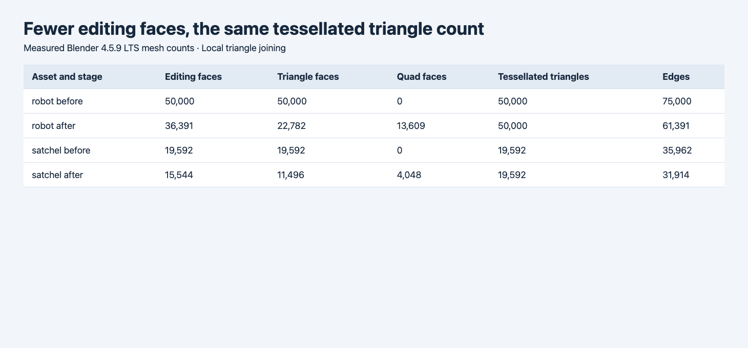
The browser table reads the measured Blender results. Editing faces count triangles and quads as individual polygons.
| Sample and stage | Vertices | Editing faces | Triangles in edit mesh | Quads in edit mesh | Tessellated triangles | Stored edges |
|---|---|---|---|---|---|---|
| Robot original | 24,994 | 50,000 | 50,000 | 0 | 50,000 | 75,000 |
| Robot after joining | 24,994 | 36,391 | 22,782 | 13,609 | 50,000 | 61,391 |
| Satchel original | 17,775 | 19,592 | 19,592 | 0 | 19,592 | 35,962 |
| Satchel after joining | 17,775 | 15,544 | 11,496 | 4,048 | 19,592 | 31,914 |
For this operation a quad comes from two triangles, so every successful join reduces the editing face count by one. The robot’s face count dropped 27.2%. Its new 22,782 triangles plus twice the 13,609 quads yield 50,000 triangles after tessellation. For the satchel the corresponding reduction is 20.7%, and 11,496 plus twice 4,048 yields 19,592. We verified those counts with Blender’s loop triangulation rather than relying on the arithmetic alone.
The sorted vertex-coordinate lists also had identical hashes within each pair. This rules out vertex-coordinate changes as a cause of render differences in these samples. The topology changed because some shared edges disappeared. It remains possible for tessellation to choose a different diagonal or for shading interpolation to change. A position hash and a triangle count are useful controls, with the rendered image and target mesh behavior checked separately.
Read the stored edges at the places you need to edit
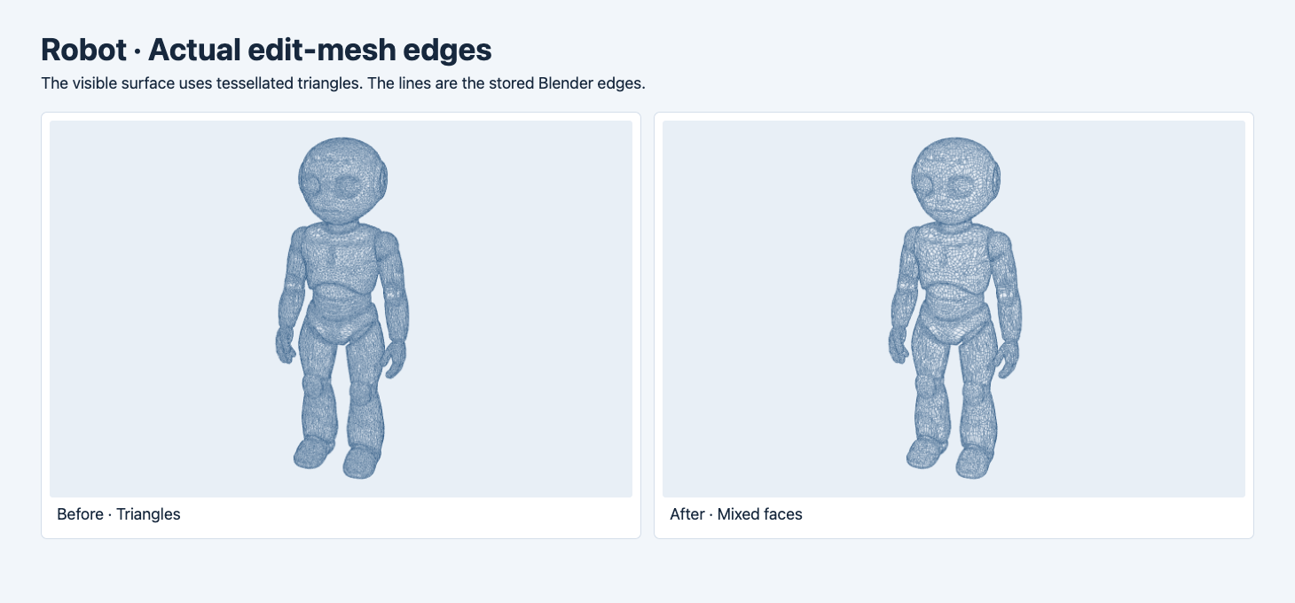
The surface is tessellated for display. The blue lines come from the stored editing edges, which makes the removed diagonals visible.
The robot’s chest and upper legs show larger cells after the join. Dense edges remain near the hands, face and joint transitions. The editing view is less crowded where triangles could be paired. You can use that as a starting point for inspecting the surface, but a mixed mesh with many quads does not establish clean loops around elbows or knees. For a rigged character, inspect the loop flow and test deformation in a separate pose experiment.
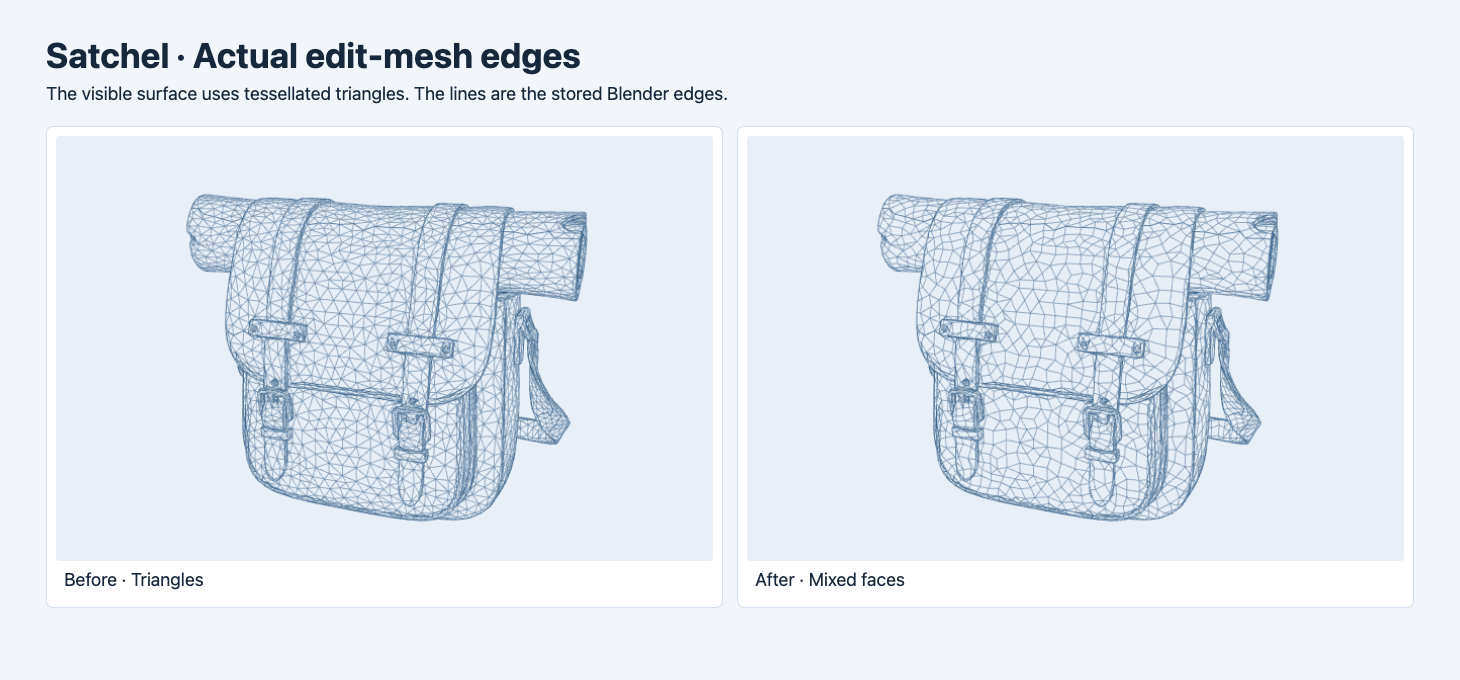
The bag’s front panel and the rolled section illustrate which diagonals disappeared under the same operator settings.
On the satchel, the broad front flap shows larger four-sided cells. Around the buckle loops, narrow straps and seams, many small edges remain. If the next task is selecting or modifying the flap, inspect those edges and the material boundary in Blender. If the next task is reaching a triangle budget, the edit-edge screenshot cannot tell you how many triangles will be sent to the renderer. Use the actual exported accessor count.
Check how the materials render after the topology edit
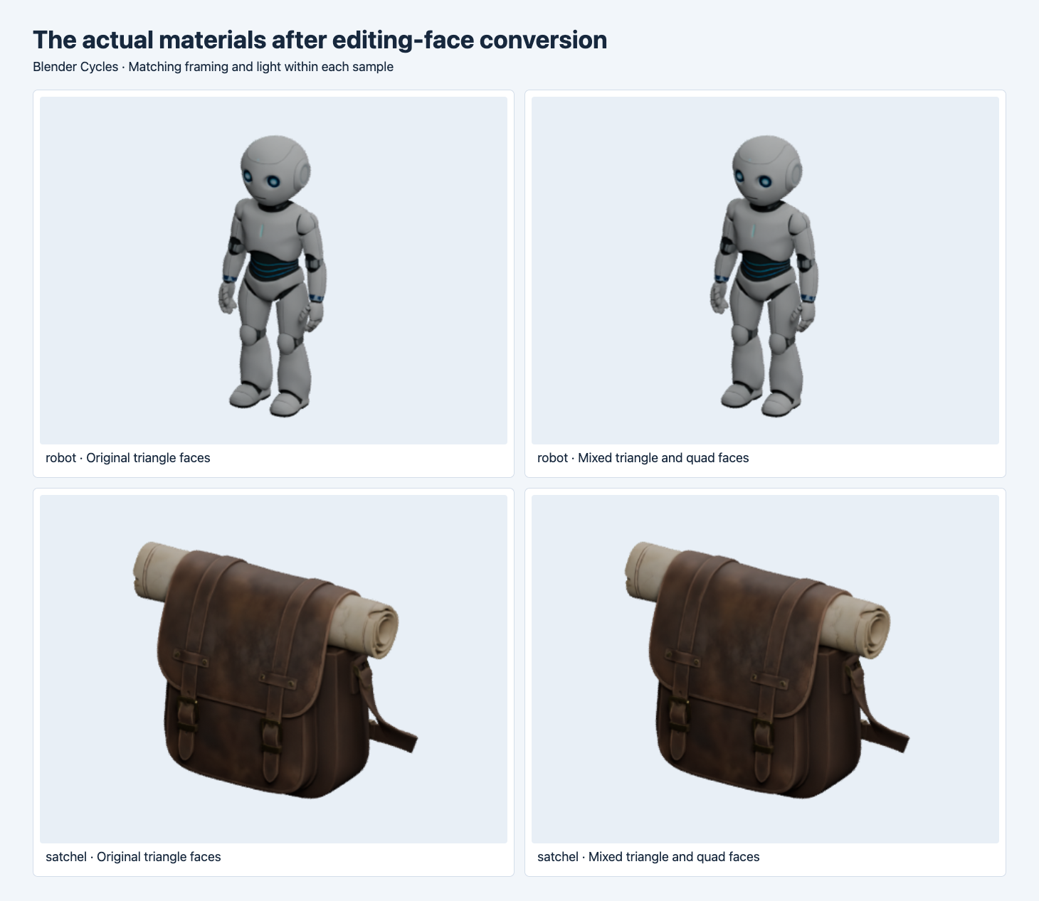
Within each row, the camera and lights match. The robot has its external texture restored and packed in both test scenes. The satchel uses its imported texture maps.
We rendered two 470 × 350 views for each asset. To describe the size of the image changes, we marked a pixel as foreground if either image had nonzero alpha there. We then counted pixels with an absolute change of at least eight levels in any RGBA channel. The robot changed 32 of 20,943 foreground pixels in the first view and 16 of 20,278 in the second. For the satchel, zero pixels met that threshold in either view. The threshold is a descriptive statistic for these views. Smaller changes can still exist. The test did not measure UV coordinates for exact equality, and it does not certify deformation or texture behavior under every light.
Verify the exported GLB against the actual budget
We exported both mixed-face meshes to GLB using Blender’s exporter and inspected the resulting primitive mode and triangle index counts. The robot GLB was 15,856,644 bytes with 50,000 triangles. The satchel GLB was 1,889,128 bytes with 19,592 triangles. Both used primitive mode 4 for triangles. The export sizes are measured for the two derivatives. Comparing them directly with the original delivery package would mix format, texture encoding and mesh packaging changes. glTF primitive modes
If you are choosing a generation or remesh route, record the editable polygon types and the tessellated count independently. Inspect the model after its final export. If the requirement is a lower runtime triangle count, use a geometry reduction step and then remeasure, as in the mobile GLB budget test. If the requirement is better editing, judge the edge flow near the features your team will modify. For a GLB versus an editable package, see the four-format round trips.
Start with a generated asset from Rodin 2.5 Fast image-to-3D or inspect the topology controls on Tripo Remesh. The local tests above use Blender, so validate any model-side quad setting on its own returned file.
Record both counts in the handoff
A production report can put the editable face count beside the exported triangle count and list the format that supplied each value. A Blender scene can preserve quads for the next editor, while a GLB from the same scene may contain only indexed triangles. An importer can also split vertices for UVs or normals, so the exported vertex count can follow a different rule from the edit mesh count. In this experiment we checked the exported triangle indices directly and used the Blender positions only for the before-and-after mesh comparison.
For a handoff that needs quads, deliver a scene or format that actually carries the polygon boundaries. Include a small edge screenshot around the area the receiver will edit. If the receiver applies a strict rendered triangle cap, include a separate count for the actual delivery format and agree on how instances are treated. This avoids a case where an artist reports 36,391 faces from the editor and a web deployment rejects 50,000 triangles from the same asset.
If a visually small change matters to the project, review the material with the production camera and light. The pixel threshold here provides an observable check for two renders. It cannot tell you whether the resulting topology is convenient for a new seam or a deformation.
FAQ
Does a quad count equal the runtime triangle count?
In this test each quad tessellated into two triangles. Count the actual exported triangles if a viewer or engine applies a triangle limit.
Does Tris to Quads produce an all-quad model?
Both tested results are mixed. The operator joins compatible triangles under the selected limits. Inspect the remaining triangles and the edge flow around features that matter.
Can I assume the UVs are unchanged?
The UV-layer counts stayed the same, and the visible material comparisons were close in the measured renders. Check UV values and seam behavior directly if the project requires strict preservation.
Found this useful? Share it