Tripo H3.1 Multi-View in 2027: Two, Three and Four Inputs Tested
Six Tripo H3.1 runs compare two, three and four input views. See rear panel detail, left silhouette, measured depth and real charges.
With only front and left images, both Tripo H3.1 runs gave the equipment case a rear panel with front-like controls. Adding the back image changed what was modeled there. In both seeds, horizontal vents and a round connector mark appeared in the outputs. Our whole-back depth metric changed by much less than the visual impression. Adding a fourth image of the right side improved the left silhouette slightly for both seeds, while panel-depth results split. This six-run test shows which evidence to capture and what to verify before publishing a rotatable model.
Key takeaway
- Capture the visible controls and the side profile first. If customers can turn the product around, photograph the actual rear panel too. This case study’s third image changed the rear features in both seeds.
- Keep volume and details in separate checks. Both back inputs brought recognizable vent and connector shapes, yet whole-back mean depth changed only 0.03 and 0.49 percentage points for the two seeds.
- A right-side fourth image changed the profile. It helped left silhouette overlap in both observed runs, but only one of the two seeds improved its full back and connector depth further.
- Use the exact route’s ordering. In our SandBase requests the accepted array prefixes were front/left, front/left/back and front/left/back/right.
Keep one image set and change the input count
We used the same authored equipment case from the five-route multi-view study. It has a handle, a stepped shell, a front screen and buttons, and an asymmetric rear panel. The rear has horizontal vent slots and a circular detail inside the connector plate. Each image was rendered independently at 768 × 768 from the same mesh, with consistent orthographic framing. This controlled the subject, background, camera family and image sizes.
On November 14, 2026 UTC we submitted six jobs to Tripo H3.1 Multiview to 3D on SandBase. We used the documented prefix order, asking for 100,000 faces, standard geometry, triangles, and no PBR or texture. We ran each view count once with seed 42 and once with seed 73. There was no change to the image bytes between seeds, and we withheld the authored GLB from the model.
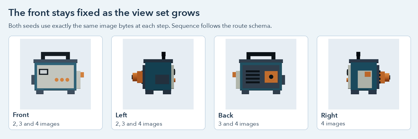
Both seeds received the same 768 × 768 images at a given count. The third image was the back. The fourth was the right.
Each result settled at $0.24 and the six jobs cost $1.44. All six completed and each original contained one GLB without any embedded image. Results ranged from 83,946 to 89,181 triangles and from 2,490,744 to 2,646,040 bytes. The observed counts remained below the 100,000 request. Adding photos did not monotonically increase triangles or file size, as the 42-seed group shows. The glTF validator reported zero errors and warnings on all six outputs.
The SandBase route wants a compact array of two to four images in the indicated order. Tripo’s direct developers’ API also documents explicit view keys and a legacy four-slot request. Check the exact interface you send to. Those direct-API examples differ from the SandBase array in this experiment. Tripo Developers multiview request formats
Compare what changed on the back
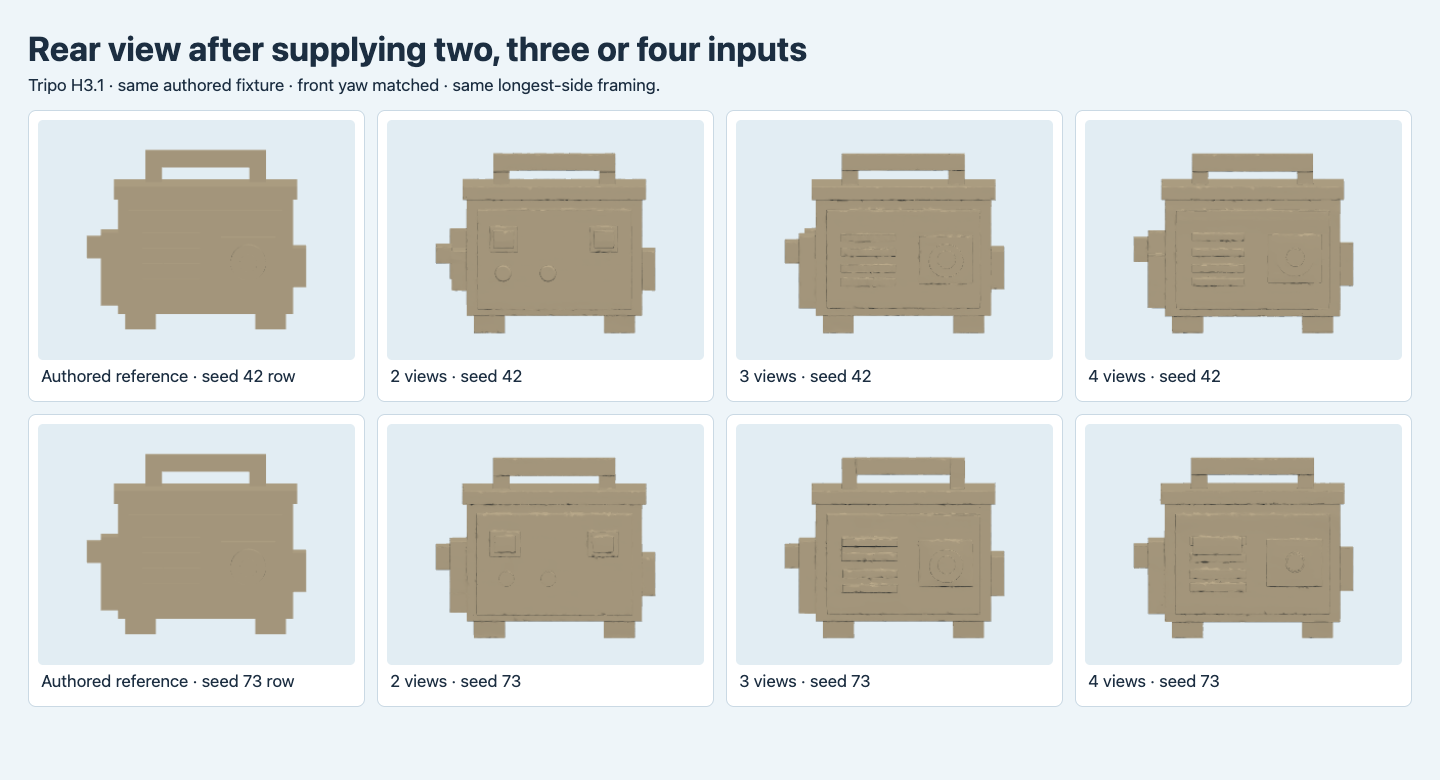
Each row has the same authored reference on the left, followed by its two-, three- and four-image outputs. The generated models use matched yaw and one neutral material.
The two-image columns show paired rectangular and round front-like marks where the reference has a vent-and-connector arrangement. The third input was the first one that showed the rear face. Both three-image results have horizontal vent geometry and a circular mark inside a rear plate. The two features stay recognizable with a fourth input, although the outlines and depth change. The same neutral material was applied to every displayed file. The source color is visible in the input panel, not baked into these screenshots.
This is a useful difference if the rear of a product needs to be recognizable in a viewer. It does not establish the location of a recess in physical units. Both three-image outputs still differed in the depth of the full back and the small connector region. Under seed 42, mean whole-back depth difference barely moved, from 19.40% to 19.37% of the normalized longest side. The fixed connector rectangle went from 10.01% to 10.32%. Under seed 73, the whole-back difference went from 20.12% to 19.63% and the connector difference from 10.45% to 10.30%.
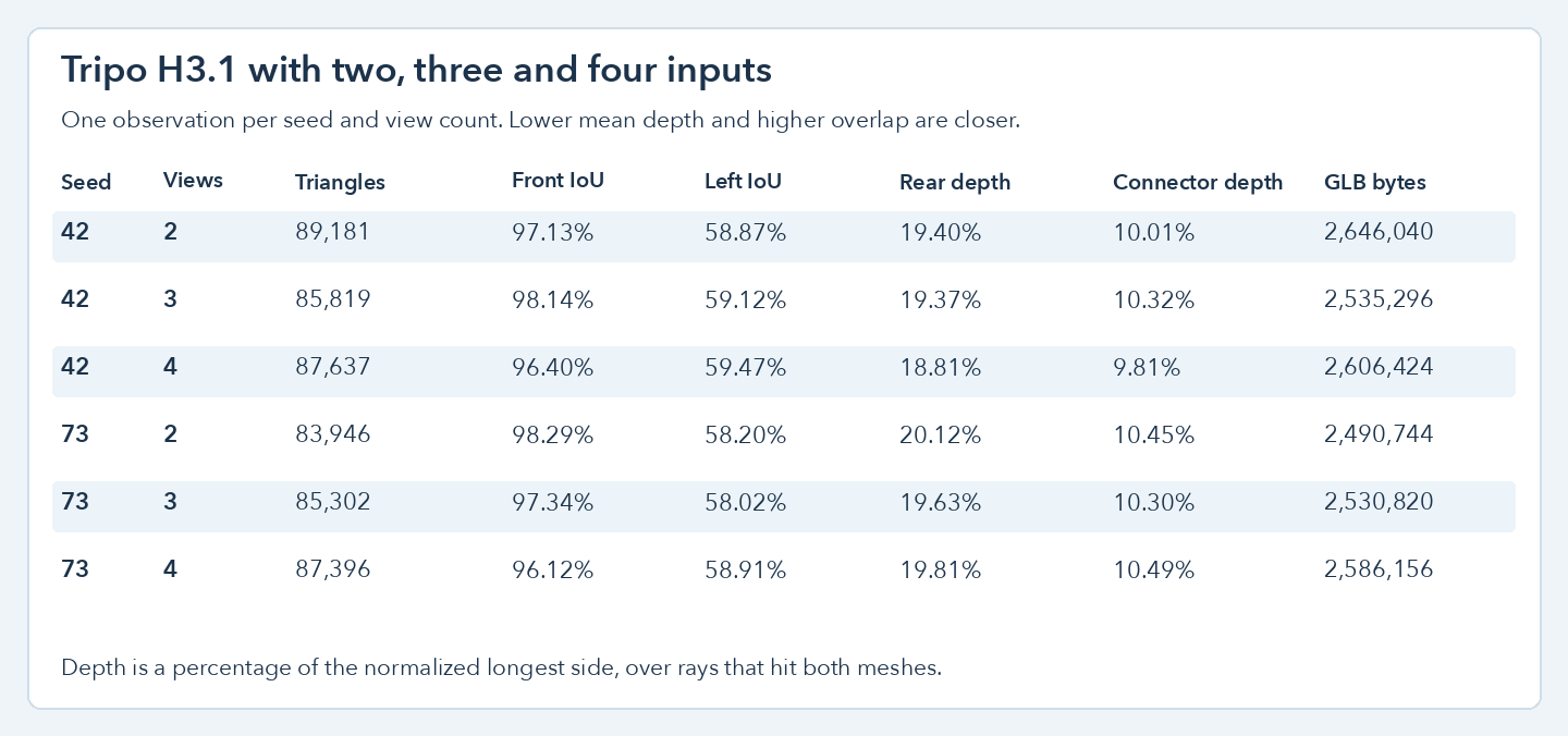
Depth uses only rays that hit both the reference and one output. Values are percentages of the normalized longest side. The numbers describe these two seeds.
| Seed | Inputs | Front overlap | Left overlap | Whole rear depth difference | Connector depth difference |
|---|---|---|---|---|---|
| 42 | Front + left | 97.13% | 58.87% | 19.40% | 10.01% |
| 42 | + back | 98.14% | 59.12% | 19.37% | 10.32% |
| 42 | + right | 96.40% | 59.47% | 18.81% | 9.81% |
| 73 | Front + left | 98.29% | 58.20% | 20.12% | 10.45% |
| 73 | + back | 97.34% | 58.02% | 19.63% | 10.30% |
| 73 | + right | 96.12% | 58.91% | 19.81% | 10.49% |
Inspect the profile after adding the opposite side
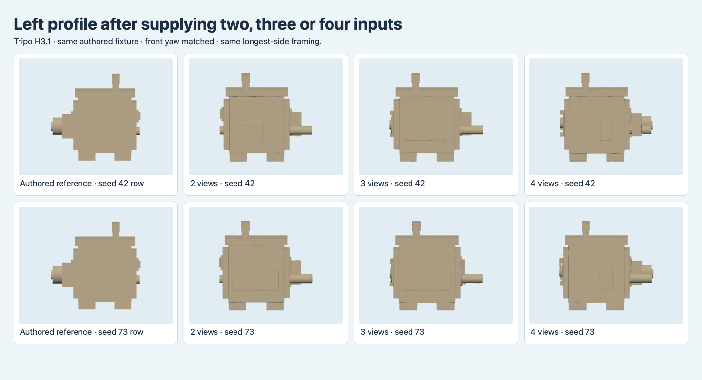
The large protrusion and small face details change across the three count settings. The camera did not move within the left-side comparison.
The fourth image showed the opposite side of the case. With seed 42, the left silhouette overlap improved from 59.12% to 59.47%, while rear depth improved from 19.37% to 18.81%. Seed 73’s left silhouette improved from 58.02% to 58.91%, but the rear worsened from 19.63% to 19.81% and the connector from 10.30% to 10.49%. The front overlap also declined from three to four inputs in both runs. Adding a view gave a different reconstruction, with some features closer and others further away on these comparisons.
The side screenshot reveals a depth problem that the front outline can hide. The reference has its large cylindrical protrusion on the left of the frame. The generated meshes show a conspicuous protrusion to the right even after the front match. Side intersection-over-union remained below 60% for all six. A viewer that opens only on the front would miss most of that discrepancy. If the object needs to fit a product outline from the side, include the profile in acceptance and compare directly against the source.
Measure the task your viewer needs
We loaded all outputs and the reference into Blender 4.5.9. Each mesh was independently centered and scaled by its longest dimension. The report casts a 128 × 128 orthographic grid from each of six directions. We evaluated four quarter turns and selected yaw by maximizing front intersection-over-union minus front mean depth difference. All six used 270° under this convention. The back and side observations came after that match, so they did not determine the yaw.
Overlap is the intersection of ray-hit pixels divided by their union. Mean first-hit depth is the average distance in the viewing direction on shared-hit pixels. The fixed rear connector rectangle has 725 shared pixels in all six runs. Depth at one rectangle can move differently from the rest of the face. A component can also be recognizable in the neutral render while occupying the wrong position. Keep a local crop, overall silhouette and view-limited depth check as separate acceptance fields.
These results cover one synthetic fixture, two seeds and a single documented sequence. The addition of a new angle also starts a new model generation. We did not exhaust camera combinations, repeat each seed/count for a variability estimate or test phone capture. Distinct unrelated objects or actual reflective surfaces can produce different findings. We recommend evaluating two pairs of views on your own assets when a partially hidden feature matters, using an order the route supports. Use the rotatable product GLB guide for the separate browser release steps.
For a controlled single-image example, see preparing a Tripo H3.1 input, which tests framing and background before adding views.
Frequently asked questions
Which angle should I add after front and left?
For this fixture and the SandBase array, back was the next valid documented angle and the one that showed the vents. If another interface supports view keys, check its ordering and select the camera that reveals the feature you will test.
Did a fourth view always improve the output?
The corresponding left-overlap scores rose for both tested seeds. Rear and connector-depth changes had opposite directions between seeds. The full result table lets you choose a capture set for the actual feature.
Is a model returned from a two-image request ready for a rotatable product preview?
Check the landing frame and inspect the sides beyond it. On our two-image files the back had plausible-looking controls in place of the actual arrangement. A feature on an unseen panel needs a source view and an acceptance check.
Found this useful? Share it