Hi3D 3.0 Multi-View Capture Checklist: Four Rear Inputs Tested
Hold front and side views fixed in Hi3D 3.0, then compare clean, omitted, darkened and occluded rear inputs with raw GLB geometry and depth checks.
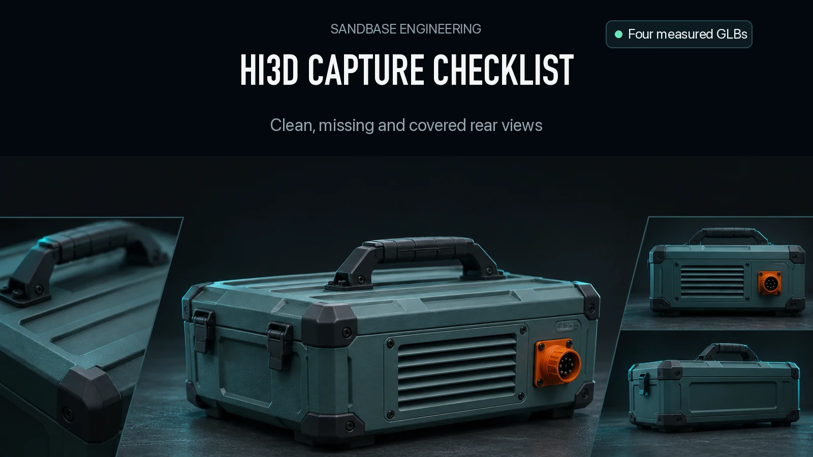
Hi3D still built four visible vent bars when the rear input was darkened to 55% RGB brightness. When we covered most of the same vent with a gray rectangle, the returned GLB carried a raised patch in that area. Omitting the rear gave it no vent pattern at all. All three variants used the same front and two side views. Capture the part you want to approve. The presence of a fourth image does not tell you whether it shows the right geometry.
Key takeaway
- Front, left and right source PNGs stayed identical. The rear image was clean, omitted, darkened to 55% brightness or covered around the vent.
- The clean and darkened rear gave the same rounded whole-rear depth difference of 1.19%. Covering the vent raised the vent-region difference from 1.95% to 7.33%. The omitted rear gave the largest connector-region difference, 10.85%.
- Each exported model requested 100,000 triangles in
2048quality, with texture and PBR off. All four completed as geometry-only GLBs and were compared with the authored case. - The setup used one synthetic object and one job per condition. The brightness adjustment and opaque overlay model specific capture problems. Real exposure behavior and general recovery rates remain unmeasured.
Label what every view is meant to show
Hi3D 3.0 Multi-View on SandBase requires the front image through image and exposes rear, left and right as named optional fields. The required front view is the anchor for this comparison. It shows a simple asymmetrical equipment case with a carry handle, control face, four feet and one visible side projection. The rear panel in the authored 3D model has four horizontal bars and an orange connector body. The sides provide some information about the rear’s outline because the connector protrudes.
The source views were local 768 × 768 renders. We used canonical named views of one unchanged mesh, no crops or shifts across cases. The 100,000-face geometry-only preset and every non-rear field stayed fixed. Reusing the four-clean-view run from the multi-view API comparison gives a reference for the tested configuration. Three subsequent jobs omit or replace only the rear slot. All four used 2048quality, no color textures, no PBR and a GLB export. The inspected route had no seed field. Use this as one observed delivery per input condition.
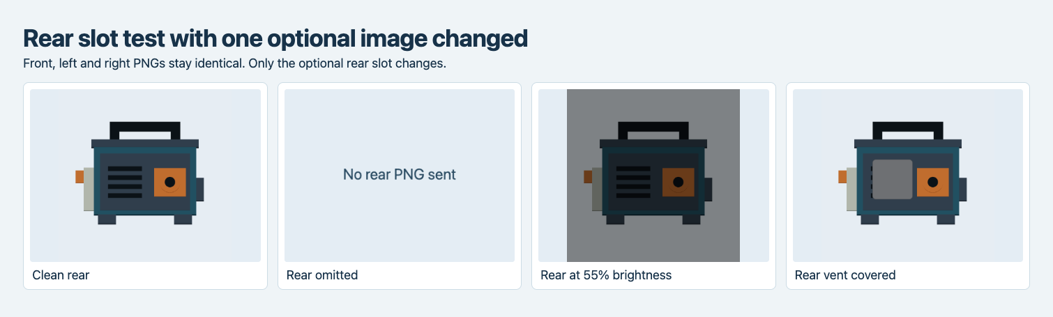
Rear comparison inputs. Darkening multiplies the entire rear image’s RGB channels by 0.55. An opaque rounded rectangle covers most of the four horizontal rear bars while the connector stays visible.
Compare what the output actually built
| Rear input | Actual triangles | GLB bytes | Front overlap | Full rear mean depth | Vent mean depth | Connector mean depth |
|---|---|---|---|---|---|---|
| Clean | 97,278 | 1,768,108 | 97.32% | 1.19% | 1.95% | 1.80% |
| Omitted | 97,490 | 1,770,652 | 97.18% | 4.47% | 3.00% | 10.85% |
| Darkened | 97,072 | 1,766,256 | 92.65% | 1.19% | 2.62% | 1.29% |
| Vent covered | 96,984 | 1,764,436 | 96.56% | 2.83% | 7.33% | 4.70% |
All four jobs settled at $2.16 each on November 14, 2026 UTC. Three new jobs cost $6.48. Including the earlier clean control, the four results represent $8.64 in generation charges. All four GLBs validated with zero errors and warnings.
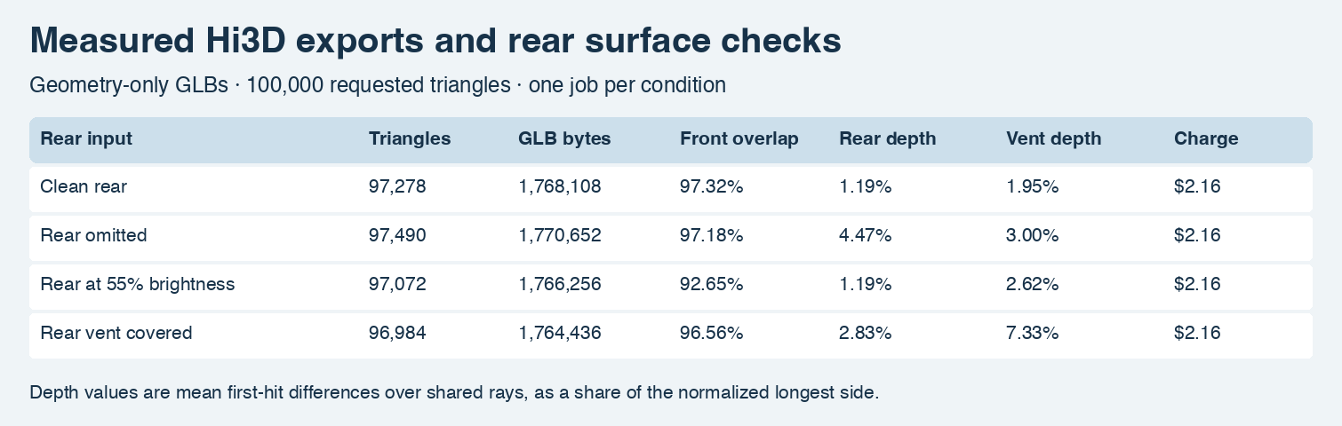
The geometry metrics are computed from the downloaded GLBs and the authored fixture. They use shared rays for depth and a separately measured silhouette.
The front kept the display, a visible handle opening and three round controls in all four outputs. Their front overlaps ranged from 92.65% to 97.32%, including a drop of 4.66 percentage points for the darkened-rear case compared with the clean case. Each request used the same front image bytes. The silhouette metric can register a changed width, foot or projection even when the primary front controls are still visible. With one delivery per case, the experiment cannot determine whether the front difference is caused by the darker rear view or ordinary run-to-run variation. Inspect the side as well as the front if that projection is needed on a store page or a game prop screen.
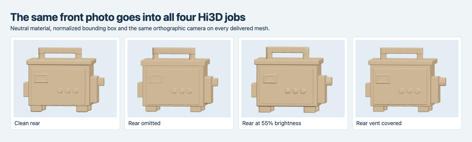
All jobs see the same control face. Each delivered mesh is centered, normalized by its longest dimension, and compared with the same camera after front-only yaw selection.
On the clean file, the vent area appears as four narrow horizontal bands in the neutral mesh. The darkened rear also showed four bands, though the lower regions look softer. In the omitted result the relevant part of the rear panel is plain, and the circular projection sits closer to the middle than it does in the reference. The covered result has the block-like surface over most of the vent, while its separate circular feature and mounting area remain visible. The gray overlay was a 2D edit. No plate was added to the 3D source mesh.
The vent and connector metrics put numbers next to the observed features. Omission had a smaller vent average than covering it, 3.00% versus 7.33%, despite leaving out the bands. The exposed rays still hit the flat back in both the simplified file and the reference, so a relatively low regional average can hide an omission. The darkened rendition even had a lower connector average than the clean one, 1.29% versus 1.80%. Do not use these four jobs to choose an exposure setting in general. Look at whether the geometry meets its intended use.
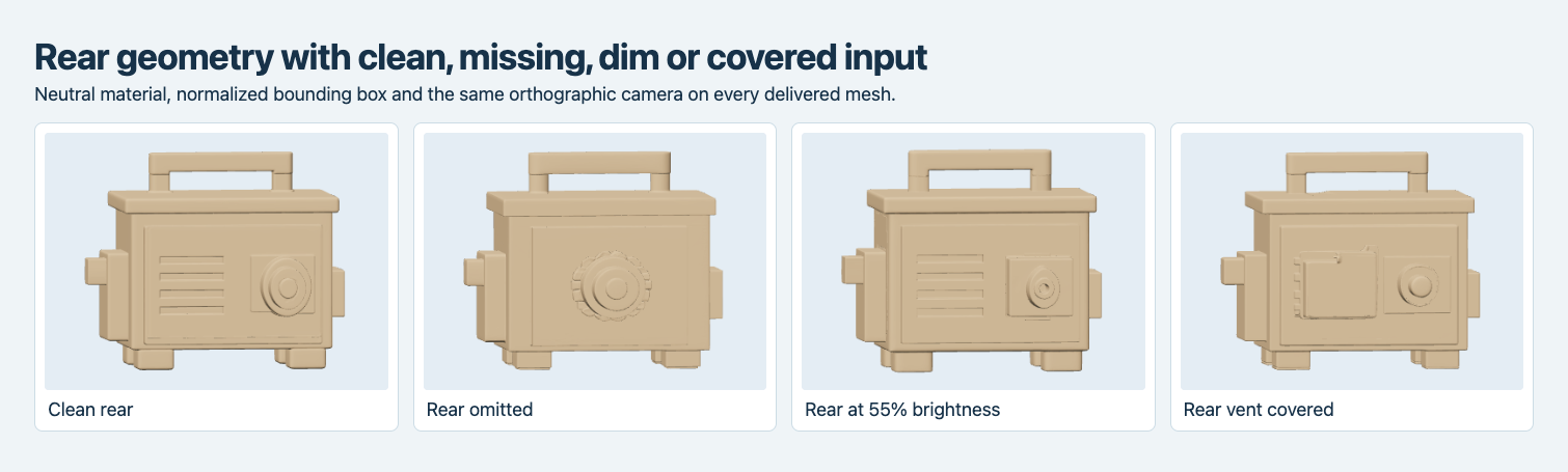
Rotate to see the detail each optional rear input was supposed to constrain. The matte finish makes the difference in geometry easier to inspect.
Use depth and outlines for different checks
We imported the original GLBs and the reference into Blender 4.5.9. Every model was centered independently and divided by its longest bounding dimension. We evaluated four quarter turns for each delivery and chose the one with the highest front silhouette overlap minus mean front depth difference. The aligned models then used the same side and rear ray grids. Aligning on the front prevents the evaluation from selecting an orientation that improves each back individually at the expense of the named front view.
An orthographic ray grid has 128 × 128 sample positions. Silhouette overlap uses the intersection divided by the union of raster hits. First-hit depth uses the shared rays and records the absolute distance along the ray between the first reference and predicted mesh hits. The average reports a percentage of normalized longest side. It leaves physical units unmeasured and gives no depth penalty for missing samples. Pair the shape measure with an actual feature check. The vent and connector regions are rectangles selected on the reference rear grid. A small whole-back mean can coexist with a local missing detail.
Shoot the image you will need to approve
Mark the intended front view in the capture folder and keep the camera setup consistent as you move around the prop. Put each image in its named slot. If a rear view is unusable, keep the original and compare a single omitted-slot result with a new, clean capture. Check whether the intended detail returns and whether any extra surface appears. For objects with both an inset and a projection, name and inspect both. A spreadsheet or issue can include a zoomed rear crop, the author-approved overall view and the exact run ID.
Keep the subject entire and centered in the capture. Before uploading, check where the case is comparatively dark and whether a real edge or feature remains visible. Masks, shadows, desk objects or hands can hide the area of interest. If the task is simply a general view of the case, its silhouette may be enough. If a particular rear profile is needed for interaction, give the engine a genuinely clear image and validate that profile on the returned mesh. This check needs a real photo or authored reference of the feature.
Record the exact input hash, role and output before comparing against a new case. In a review with a hard mesh budget, also inspect the exported count and validator report. For textured previews, restore color after checking shape and compare captured versions with the same material settings. The related Tripo H3.1 view-count experiment varies how many views reach that route, giving another example of whole-object and local-feature checks.
Frequently asked questions
Is a rear photo required?
The inspected SandBase route requires the front photo and supports optional rear and sides. The three-view case here omits only the rear. The article’s four delivered files have a fixed front and side set.
Does the 100K setting describe the exact delivered count?
Count triangles in the decoded original. The request is a target. The measured table records the file, so a downstream validation step can use the actual number.
Does a gray material validate the color or texture?
This experiment used geometry-only outputs, and the neutral screenshots evaluate geometry. Repeat the relevant checks with texture enabled if the source color or appearance is a delivery requirement.
The Hi3D single versus multi-view occlusion test extends this fixture with a single front and an isolated front-plus-rear comparison, measuring the connector height above the panel.
Found this useful? Share it