STL vs 3MF for AI 3D Printing: Size, Color and Slicing Tested
Compare STL and 3MF with two AI-generated meshes in PrusaSlicer. See imported units, file bytes, layer counts and what happens to four colors.
The same 60 mm relief produced 35 layers as STL and 3MF in PrusaSlicer. Then we encoded the coordinates in inches. The 3MF still opened at 60 mm, while the unitless STL opened at 2.362 mm and sliced into one layer. A second test with a colored mesh showed a different handoff problem. Its four display colors were present in the 3MF we created and read by Three.js, but all four were absent from the file that PrusaSlicer 2.7.2 exported on the command line. If you are sending an AI-generated model to a printer, verify scale and material transfer in the receiving tool.
Key takeaway
- Use an explicit physical dimension to check every imported mesh. An inch-valued STL needs a 25.4× scale factor in a millimeter import workflow.
- A correctly sized STL gave the same 35 layers and 2,302.13 mm of estimated filament as our millimeter 3MF for the relief. For the half-million-triangle colored mesh, the correctly sized files also had the same layer count with small differences in the toolpath estimates.
- 3MF can carry display colors, and slicer projects may carry separate print settings. In our tested 3MF round trip, the slicer’s command-line export kept all 500,000 triangles and discarded the four generic base-material display colors.
- Preserve the original delivery and save a separate printer-specific project when the destination needs paint or filament assignments. Check the output toolpaths in that project’s intended printer and slicer profile.
Export two formats from one mesh at a time
The relief is the curved-horn panel from Meshy Relief, which delivered GLB and STL on the SandBase route. We reused the existing 60 mm copy from the Rodin STL and Meshy Relief test. The second asset is the 500,000-triangle four-color GLB from Hi3D Multicolor, which we previously checked for palette and geometry. The color result has constant vertex color within each source primitive. For the printing experiment we welded identical positions, moved the model into a Z-up frame, and set its longest side to 60 mm.
For each of those two meshes we created four local files. Binary STL and 3MF each got one copy with millimeter-valued coordinates and one with inch-valued coordinates. 3MF explicitly declared unit="millimeter" or unit="inch". The STL coordinate payload had no unit metadata. For the colored example the 3MF also got four core base-material references, derived from the original GLB palette. These were model packages we made after generation. We used the same indexed triangle set to write both formats, without remeshing. PrusaSlicer reported one manifold part for each import, with the triangle count shown below. These checks describe the tested files and do not establish that either object is ready for physical manufacturing.
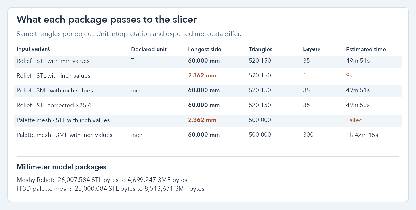
PrusaSlicer 2.7.2 on Linux read a 2.362 mm longest side for the uncorrected inch-valued STLs. Estimates shown come from the same local slicing profile.
Check scale before judging the slicer’s preview
Binary STL records triangles as coordinates and normals. A file can store numbers that describe inches, millimeters, or a model space with no physical convention. The recipient needs to know which was intended. The 3MF Core format has a model unit field and defaults to millimeters when it is absent. We chose both explicit values for the test. 3MF Core Specification · PrusaSlicer format support
| Model and file | Imported X × Y × Z | Facets | Layers | Estimated time |
|---|---|---|---|---|
| Relief, millimeter STL | 59.070 × 60.000 × 6.999 mm | 520,150 | 35 | 49m 51s |
| Relief, millimeter 3MF | 59.070 × 60.000 × 6.999 mm | 520,150 | 35 | 49m 51s |
| Relief, inch-valued STL | 2.326 × 2.362 × 0.276 mm | 520,150 | 1 | 9s |
| Relief, 3MF marked inch | 59.070 × 60.000 × 6.999 mm | 520,150 | 35 | 49m 51s |
| Relief, STL corrected ×25.4 | 59.070 × 60.000 × 6.999 mm | 520,150 | 35 | 49m 50s |
| Palette mesh, millimeter STL | 54.682 × 50.878 × 60.000 mm | 500,000 | 300 | 1h 41m 46s |
| Palette mesh, millimeter 3MF | 54.682 × 50.878 × 60.000 mm | 500,000 | 300 | 1h 42m 18s |
| Palette mesh, inch-valued STL | 2.153 × 2.003 × 2.362 mm | 500,000 | No output | — |
| Palette mesh, 3MF marked inch | 54.682 × 50.878 × 60.000 mm | 500,000 | 300 | 1h 42m 15s |
| Palette mesh, STL corrected ×25.4 | 54.682 × 50.878 × 60.000 mm | 500,000 | 300 | 1h 42m 15s |
The slicing profile uses a 0.4 mm nozzle, 0.20 mm first and subsequent layers, three perimeters, 20% infill and supports off. The mesh and output are tests on the computer. We did not print a part, measure print time on hardware, or approve supports for the upright palette model.
Notice that the uncorrected versions kept their face counts. The relief still exported G-code, but its longest side was about one twenty-fifth of the intended dimension. Its 9-second estimate corresponded to 1.45 mm of estimated filament and one layer. The 60 mm versions used roughly 2.30 m of filament across 35 layers. The palette STL with inch values failed at G-code export because the first layer had no extrusions. The same size error produced two different outcomes. Checking the imported bounds would catch both before starting a print.
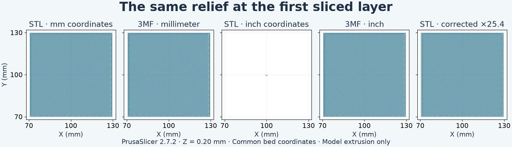
All five frames use the same bed coordinate range at Z = 0.20 mm. The tiny central trace in the third panel comes from interpreting bare inch values as millimeters.
The ×25.4 correction reproduced the intended long side and recovered the expected layer counts for both STLs. Use that factor when the source unit is confirmed as inches. Generated meshes often have an arbitrary size, so record an intended length first, then scale by target length divided by imported length. Check all three axes afterwards, especially when width must fit an opening or a base has a minimum wall thickness.
For a known source unit you can reproduce the import check before slicing. These commands use the same PrusaSlicer CLI pathway as the test.
prusa-slicer --info source.3mf
prusa-slicer --info inch-values.stl
prusa-slicer --scale 25.4 --info inch-values.stl
prusa-slicer --scale 25.4 --export-gcode --layer-height 0.2 \
  --first-layer-height 0.2 --nozzle-diameter 0.4 \
  --no-support-material --output corrected.gcode inch-values.stl
The test builds of the millimeter 3MF were smaller too. The relief fell from a 26,007,584-byte binary STL to a 4,699,247-byte 3MF. The colored mesh went from 25,000,084 bytes to 8,513,671 bytes even with four material entries. Binary STL repeats vertex coordinates for each facet. Our 3MF stores indexed vertices and compresses the XML in a ZIP package. These are comparisons of the actual uncompressed STL and compressed 3MF files. They do not predict the ratio for a separately zipped STL or a full 3MF project with additional data.
Verify color in the package, receiving tool and printer setup
We converted each uniform GLB vertex color from its linear RGB value to sRGB, then wrote it as one 3MF base material’s displaycolor. Of the 500,000 triangles, the four palette entries covered 264,038, 162,866, 73,006 and 90 triangles. The local 3MF packages contain material references for all of them. Three.js’s 3MF loader read the four material values. The STL uses a single neutral viewer material because our binary export had geometry only.
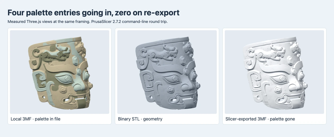
The left shows the local package’s four display colors. The center and right use each viewer loader’s neutral presentation. All three display 500,000 triangles.
PrusaSlicer 2.7.2 read the geometry and inch or millimeter unit from both inputs. Its CLI model export omitted the generic basematerials entries and triangle palette references for both packages. Inspecting the ZIP and rendering the exported copy independently confirmed the color payload was gone. Single-extruder G-code contained no tool-selection commands. That was the profile we sliced with. It tests a specific import and export workflow and says nothing about a manually painted PrusaSlicer project or a current multicolor profile in another slicer.
The core 3MF display color is a rendering property. It helps software show a material but does not select a spool or teach a printer which regions to manufacture in which material. A slicer project is another handoff. PrusaSlicer projects can keep slicer-specific settings, and its multi-material painting workflow maps regions to configured extruders. If color matters, assign the actual filaments in the destination project and inspect the sliced preview by tool before shipping the file. PrusaSlicer project files · Prusa multi-material painting
Decide what to send to the printer
A verified STL with millimeter-valued coordinates is useful when the recipient only needs the single-color surface. Include one check dimension and the intended orientation. If they will import a model package, 3MF can keep the physical units explicit and provide a smaller payload on meshes like the ones tested. If they need to run a color job, send a project created in their target slicer after confirming the printer, extruders, planned regions and preview. Keep the original, scale-corrected mesh, and printer project identifiable so the next person can redo only the part of the workflow that changed.
Frequently asked questions
Does converting STL to 3MF change print quality?
When the imported size and geometry are equivalent and the same settings are used, a container conversion does not add detail. Our relief had the same 35 layers, estimated time and filament length in both correctly sized millimeter files. Small toolpath differences can still occur after serialization and rounding, as the palette estimates show.
How do I tell whether a 3MF has print settings?
Open it in the intended slicer and check the project import summary or inspect the ZIP contents. A core model can carry color, unit and geometry. Slicer-specific project metadata and filament assignments depend on how the package was created.
Can 3MF recover missing color from an STL?
A conversion can set an agreed unit and package the triangles. It cannot recover the original GLB’s palette from a geometry-only STL. Keep the original color asset, then map its regions in the receiving print workflow.
Found this useful? Share it