Meshy Relief Depth and Base Thickness in 2027
Compare three Meshy Relief exports from one image. See measured STL depths, base thickness, horizontal slices, file sizes and actual charges.
On the same horn image, Meshy Relief produced a 3.998 mm thick STL in Low mode with a 1 mm plate. High with the same plate produced 6.999 mm. Keeping High and requesting a 3 mm plate brought the total to 8.999 mm. The three exports have the same footprint, triangle count and binary STL size. A shared cross-section shows where the extra thickness went, and the original depth maps show why one image code cannot be read as a physical dimension.
Key takeaway
- The low and high presets with a 1 mm base reached about 2.998 and 5.999 mm above the flat background respectively. Both had the same bottom at −1 mm.
- Increasing the High base to 3 mm moved the bottom to −3 mm and kept the highest point at about 6 mm. The two High jobs still returned different depth maps and slightly different surface profiles.
- All three STLs measured approximately 59.070 × 60.000 mm in plan. Each had 520,150 triangles and a size of 26,007,584 bytes. They had zero open edges or edges used more than twice under the exact-position inspection.
- Each completed job cost $0.80. The GLB is useful for visual review, the STL supplies the physical geometry, and the 16-bit map preserves the encoded depth field.
Keep the photo, width and sampling fixed
We used Meshy’s public example of a curved, decorated horn, with a transparent background and raised-looking bands around the lower arc. The source PNG is 629 pixels wide and 642 pixels tall. We sent the same public image to Meshy Relief on SandBase three times on November 14, 2026. All three requests specified a 60 mm longer side, a mesh resolution of 512, emboss mode, no bend and a retained base plate.
The first two requests selected Low and High with a 1 mm base. The third selected High with a 3 mm base. We left carving_depth_mm unset. Meshy’s direct documentation describes Low and High as different depth styles and lists default carving depths of 3 and 6 mm respectively. The two presets therefore change both the style of the depth map and the default carving amplitude. The trial compares the presets as a reader would use them with the default depth. Meshy Relief API documentation
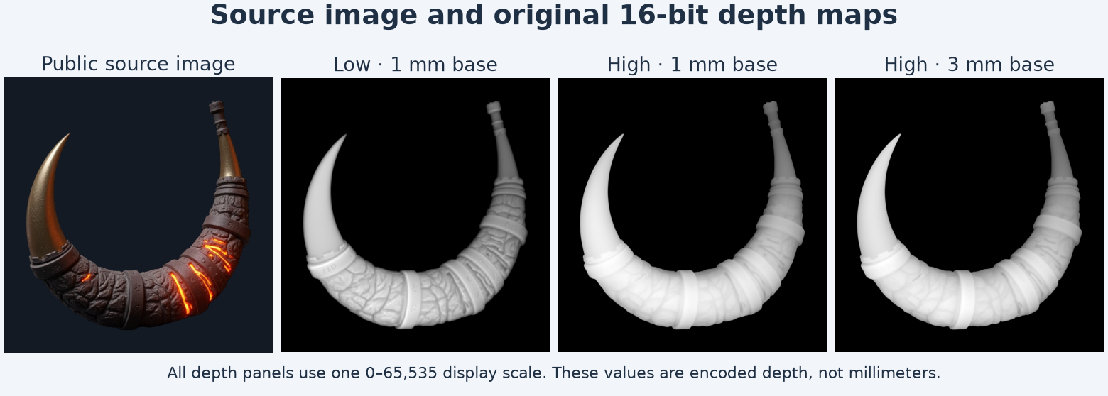
The depth images are displayed on one scale from 0 to 65,535. The input is shown on a dark background for contrast.
Each job returned one GLB, a binary STL, a depth PNG and a thumbnail link. The three original depth maps decode as 16-bit grayscale at 2,032 × 2,064 pixels. That is a different grid from the requested mesh resolution. The same 512 setting produced a mesh at the same triangle count in these exports. Use the dimensions of the actual files if another stage expects either a texture image or a fixed-size mesh.
Measure the plate and the raised surface
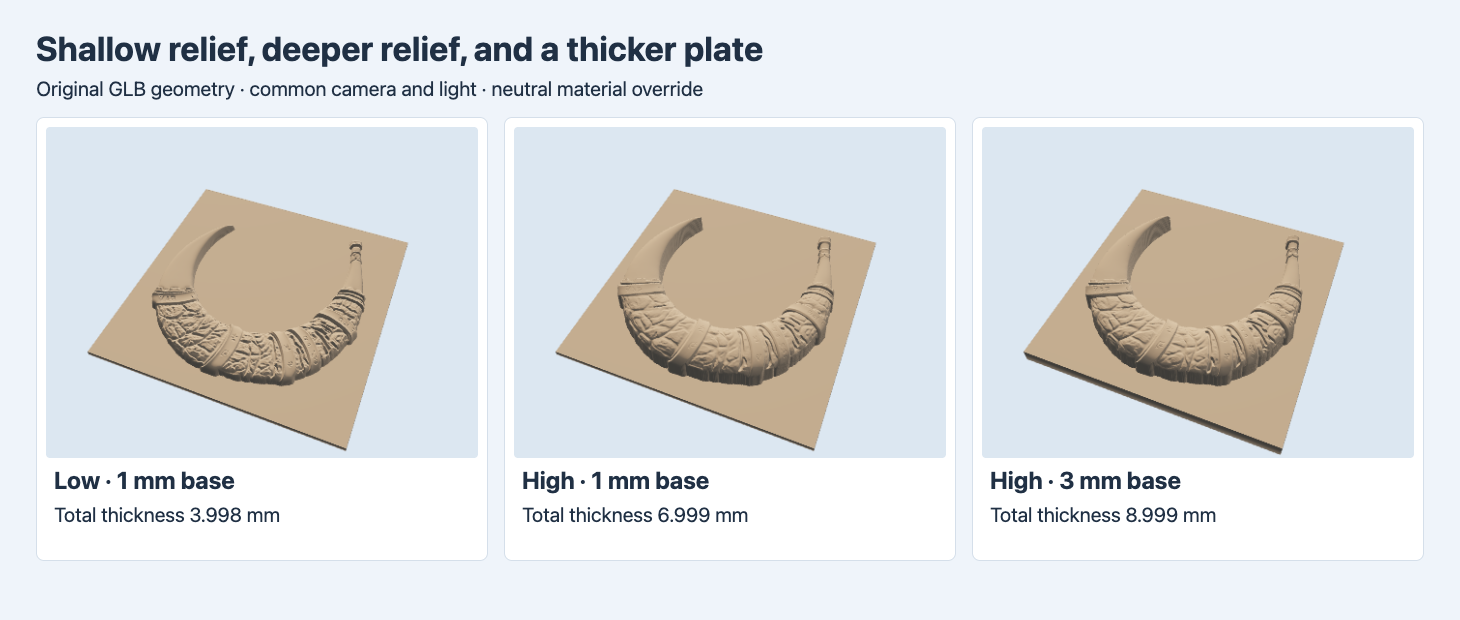
The three original GLBs use one neutral material for comparison. The scene has a shared camera, light and scale. The render shows the geometry without the input image colors.
The Low result has shallower sidewalls around the horn and visible fine relief along the lower curve. The two High results rise farther out of the background and have steeper walls at the edge in this view. The third plate also shows a thicker front edge. Viewing all three from the same position prevents a lower or closer camera from making the deeper profile appear larger than it is. For a plaque that must slide into a frame, measure the envelope from the back of the plate to the highest point and compare that with the frame’s clearance.
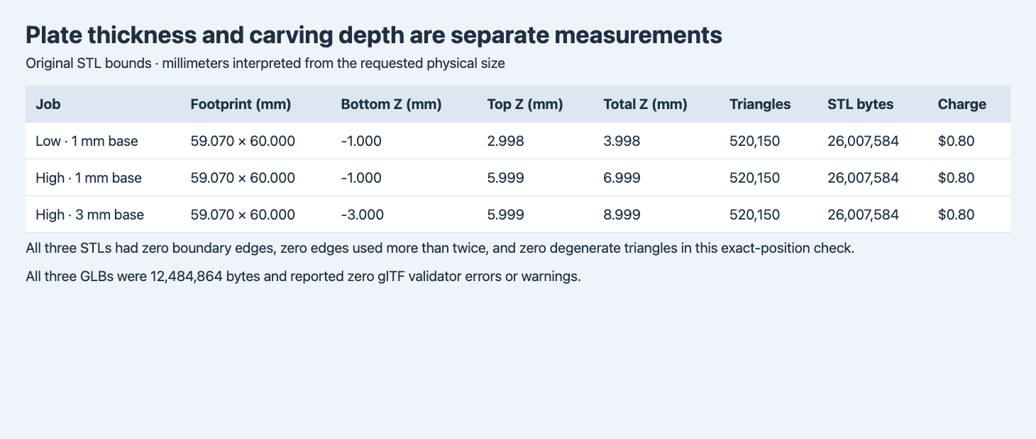
The STL coordinates are interpreted in millimeters using the requested 60 mm size. The table lists the back face and tallest vertex separately.
| Preset and requested plate | Bottom Z | Highest Z | Total thickness | STL triangles | Actual charge |
|---|---|---|---|---|---|
| Low, 1 mm | −1.000 mm | 2.998 mm | 3.998 mm | 520,150 | $0.80 |
| High, 1 mm | −1.000 mm | 5.999 mm | 6.999 mm | 520,150 | $0.80 |
| High, 3 mm | −3.000 mm | 5.999 mm | 8.999 mm | 520,150 | $0.80 |
The coordinates came from vertices in the original binary STLs. STL itself has no unit field. The 60-unit longer side matches the 60 mm requested size, and the GLB coordinates are 1,000 times smaller along the same axes, consistent with millimeters in these STL files and meters in GLB. Verify the footprint after import into your own software because an import setting can interpret the same coordinates at a different scale. The three GLBs were each 12,484,864 bytes, with zero errors and warnings from the glTF validator. The three STL files were each 26,007,584 bytes. The GLBs split their geometry across two primitives with 514,066 and 6,084 triangles. The sum of 520,150 matches each corresponding STL. The test cost $2.40 across the three relief jobs.
Read the same cut in all three STLs
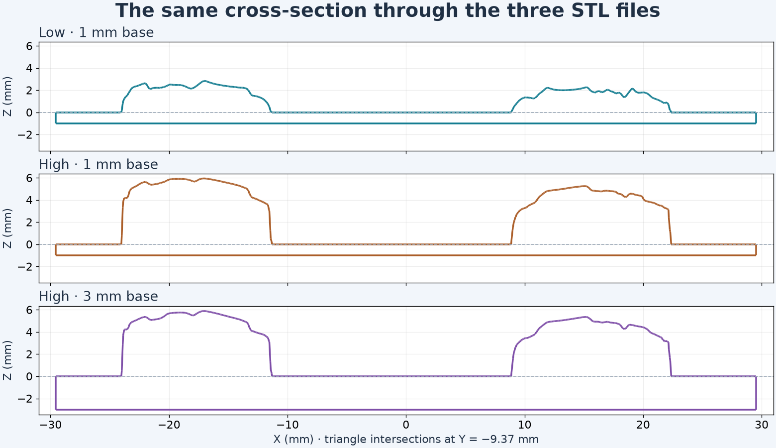
The plot intersects the triangles with the same plane in each file and uses the same vertical scale. The dashed line is the flat background at Z = 0.
At Y = −9.37 mm, the cut passes through both arms of the curved horn. The Low crest in that slice reaches 2.841 mm. The two High crests reach 5.947 mm with the 1 mm plate and 5.890 mm with the 3 mm plate. The bottom of the plate stays at −1 mm in the first two rows and drops to −3 mm in the third. These values differ from the whole-mesh maximum because a fixed cut can miss the single tallest point.
The two High jobs are separate runs. Their depth maps are not byte-identical. Across pixels where at least one of the two maps has a nonzero value, approximately 0.023% of the pixel codes match exactly. This is a test of exact 16-bit equality, which is sensitive to small changes, and it does not measure perceived difference. We can confirm the change in plate geometry from the bottom coordinate and compare the upper profiles. The trial cannot determine whether the depth-map difference comes from rerunning the model or from the plate setting.
The cross-section is a direct mesh measurement. It does not encode toolpath, infill, print supports or a choice of layer height. For a tight thickness tolerance, check a fixed section through the area that must clear a frame, then measure the global envelope to catch taller features elsewhere. If you need to constrain carving height independently of the preset defaults, set an explicit carving depth and measure the delivered mesh again.
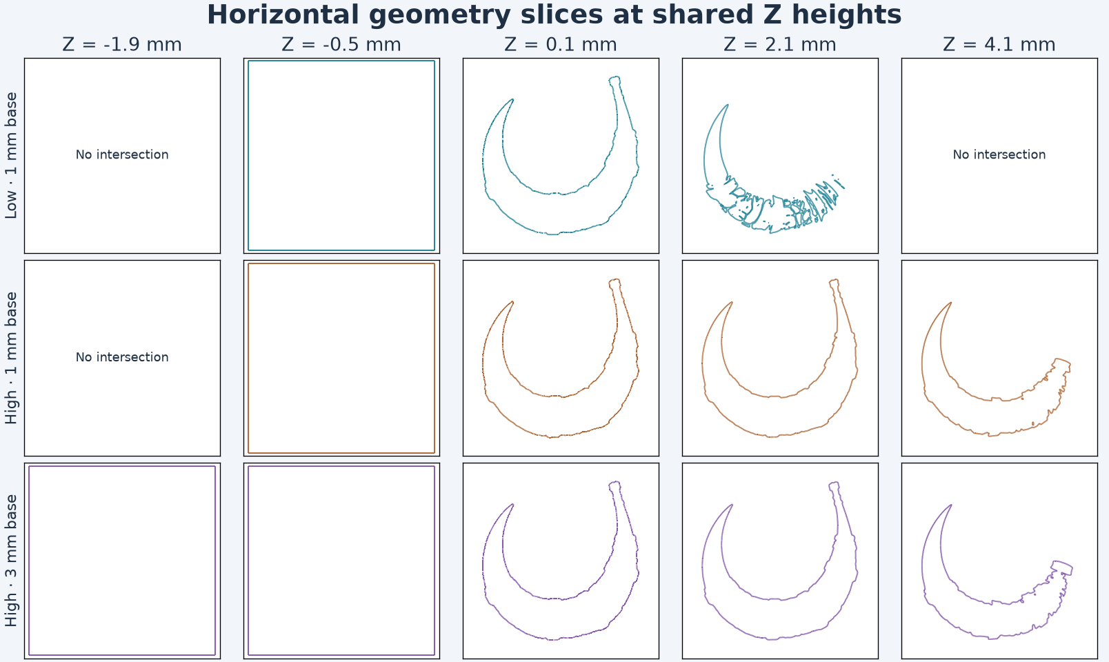
The panels show only intersections of the geometry at the indicated heights. No printer profile or toolpath is involved.
At −1.9 mm, only the thick plate intersects the plane. At −0.5 mm, all three produce their rectangular outline. At 2.1 mm, the Low file shows separated and irregular regions around the lower horn, while the two High files retain a more continuous silhouette at this height. At 4.1 mm the Low file has no intersection. These coordinates use the original zero-height background. A slicer that drops the back onto the build plate will shift the displayed heights by 1 or 3 mm.
Inspect the mesh before slicing
For the STL check, we grouped vertices that shared the same stored position. We counted how many triangles used each undirected edge and checked for faces with zero area. Each file had zero boundary edges, zero edges used by more than two triangles and zero zero-area triangles. This establishes those specific properties under the inspection. A slicer still has to generate usable paths at the selected scale and print profile. We did not evaluate print material, nozzle width, supports, warping or physical fit.
Use the three original outputs for different checks. A shaded GLB makes it easy to compare the shape and base thickness under one camera. The STL contains the physical geometry used for dimensional checks. The depth map supports numerical analysis of the source field, where the values are encoded from 0 to 65,535. Check the actual returned mesh before treating any of those codes as a height. For more context on import and scale, see GLB, FBX, OBJ and STL round trips.
Here is the High request with the thicker plate. Use a server-side bearer token for POST https://api.sandbase.ai/v1/run, then poll the returned ID using GET /v1/run/{id}. Substitute your own accessible input image if you want to test a production asset. Each run can incur a charge.
{
  "model": "meshy/relief",
  "image": "https://static.sandbase.ai/examples/meshy/relief/input_image_0.png",
  "variant": "high",
  "size_mm": 60,
  "mesh_resolution": 512,
  "carving_mode": "emboss",
  "base_thickness_mm": 3,
  "remove_base": false,
  "bend_mode": "off"
}
Keep the source image hash and output hashes next to the settings. Compare the preview, overall dimensions, local section and mesh checks before choosing a file. A shallow preset can be a better fit when a mount gives little room above the plate. A deeper preset leaves more relief to catch side light, and it also increases the space needed at the highest point.
The same High STL appears in our Rodin versus Meshy comparison, which shows the different profiles of a freestanding part and a relief plaque at the same planar span.
FAQ
Does the plate thickness describe the whole object?
In these embossed examples the base sits below the zero-height background. Total thickness is the difference between the highest vertex and the plate bottom. For the High trial with a 3 mm base, that was 8.999 mm.
Does High increase the number of triangles?
All three original STLs had 520,150 triangles at mesh resolution 512. This is the measured result for the one image and the settings above. Check actual counts when changing resolution, image aspect ratio or the base settings.
Can I compare the maps by looking at the grayscale image?
Use a shared grayscale range and keep the original 16-bit files if numerical differences matter. Compare raised heights in the original STL after interpreting its scale.
SandBase ran and billed the three trials. Figures use the original geometry and original depth maps. The cover is illustrative.
Found this useful? Share it