From Photo Relief to a Sliced Tag with Meshy
Three Meshy relief jobs and four PrusaSlicer plans measure local lettering, tag thickness, and a 3.6 mm hanging hole.
A 0.4 mm relief setting left the raised A7 marks just 0.040–0.042 mm above their nearby surface on a 48 mm tag. In PrusaSlicer, the selected top layer carried fragments of the large and medium characters. Keeping the same image and requesting 1.2 or 2.4 mm gave recognizable large-letter contours and different small-letter strokes. We measured the original STL files, sliced all three, then added a 3.6 mm hanger hole to the deepest copy and checked its actual first-layer plan.
Key takeaway
- Three Meshy Relief requests used one 768 × 512 source, the
lowvariant, a 48 mm long side, a 1.8 mm backing and a 512-point long-side mesh setting. Only the carving-depth request changed. Each settled at $0.80. - Measured overall STL thicknesses were 2.199, 3.000 and 4.187 mm. The 2.00 mm-tall source letters had local median rise of 0.040, 0.171 and 0.268 mm.
- With a 0.4 mm nozzle and 0.2 mm layers, PrusaSlicer produced 11, 15 and 21 layers with model extrusion. The 5.50 mm source characters remained recognizable in both stronger settings at the selected inspection layers.
- The deepest copy with a Boolean-cut hole measured 3.600 mm through the backing in both tested directions. PrusaSlicer estimated 22 minutes 28 seconds and 1,188.83 mm of PLA filament for that digital test piece.
Start with a picture that can expose lost detail
We built one photo-style render of a graphite tag in Blender. Its 48 × 32 mm camera field contains A7 rows designed at 5.50, 3.25 and 2.00 mm tall. Three pairs of narrow bars at left have nominal gaps of 0.45, 0.80 and 1.20 mm. This fixture gives us three scales of lettering and a place to check whether two close strokes stay separate. The blank space on the left also leaves room for a hanger hole at a fixed location.
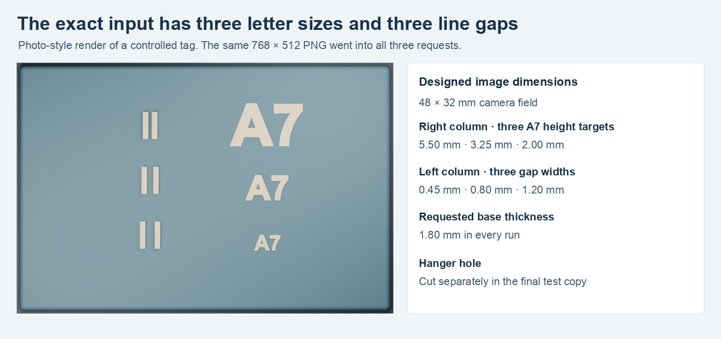
The 768 × 512 image on the left is exactly what the three requests received. The design sizes on the right identify the features later checked in the mesh and sliced layers.
We uploaded the same PNG for all three calls on November 14, 2026 UTC. We set variant: "low", size_mm: 48, mesh_resolution: 512, carving_mode: "emboss", base_thickness_mm: 1.8, remove_base: false and bend_mode: "off". The three carving_depth_mm values were 0.4, 1.2 and 2.4. The setting controls the relief pipeline, and the actual rise of an individual letter comes from the returned mesh. We made one request at each depth to check this reference geometry.
For a new tag, it helps to leave a clean flat region for dimension checks and the hanger hole. A front-facing picture exposes the outline and both edges of a letter. Our source used a controlled frame so the expected positions were known down to the render scale. The same measurement method can use a photo with a visible ruler or a known outline as its scale reference.
Measure thickness and lettering in the actual STL
Every response included a GLB, an STL and a depth preview. The three binary STLs each held 353,614 triangles and 17,680,784 bytes. Each measured 48.000 × 32.102 mm in plane after interpreting the coordinates as millimeters to match the requested long side. STL carries coordinates without a unit field, so confirm the span after import. In this case the minimum Z was −1.800 mm in all three. The maximum Z varied with the depth setting.
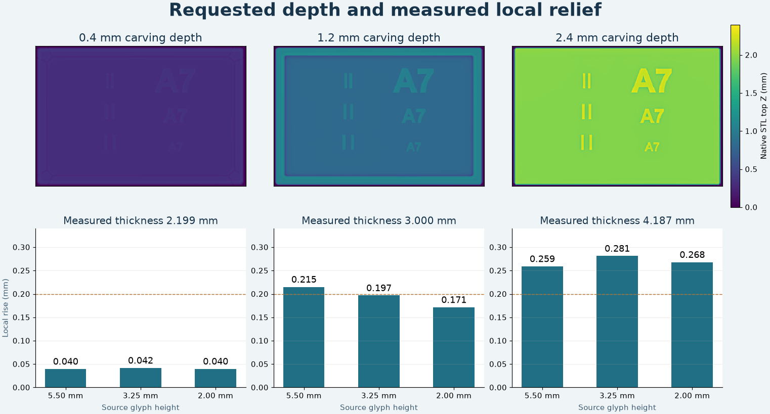
The top row uses one native Z scale. The lower charts compare each projected glyph silhouette with adjacent substrate patches. The dashed line is the 0.2 mm slice spacing used below.
| Requested carving depth | Overall thickness | Rise at 5.50 mm A7 | Rise at 3.25 mm A7 | Rise at 2.00 mm A7 |
|---|---|---|---|---|
| 0.4 mm | 2.199 mm | 0.040 mm | 0.042 mm | 0.040 mm |
| 1.2 mm | 3.000 mm | 0.215 mm | 0.197 mm | 0.171 mm |
| 2.4 mm | 4.187 mm | 0.259 mm | 0.281 mm | 0.268 mm |
We cast 98,304 downward rays per STL on a common 384 × 256 grid. We projected the authored glyphs at the same sample positions to get 1,643 large, 582 medium and 218 small letter pixels. Each row was measured independently by subtracting the substrate median in an adjacent window from the median on its silhouette. This compares the area that should stand out to its local plate. The 2.4 mm request reached an overall relief peak close to the full budget, but the smallest row stood 0.268 mm above its own surroundings. A large depth span across the whole tile can coexist with subtle lettering.
For a geometry check, we grouped identical positions in each STL and counted undirected triangle edges. All three had zero single-use edges, zero edges used by more than two faces, and zero zero-area triangles. Those measurements cover topology around the original plate. The height sample and slice answer the separate question of how much of a letter survives the selected resolution.
The distribution at the smallest row adds a layer-scale check. Relative to its local background median, 72.02% of the letter-mask hits in the 2.4 mm case rose by more than 0.20 mm. The other two cases had zero hits over that cutoff in the same row. That explains why inspecting just the overall tile thickness misses a difference at the smallest label.
At the three test bar pairs, we also compared the top height at the designed gap center with the lower of the two bar-center medians. The shallow version produced only 0.041–0.055 mm of difference. The 1.2 mm case ranged from 0.191 to 0.231 mm, and the 2.4 mm case from 0.322 to 0.398 mm. This checks vertical contrast across the valley. The nominal 0.45, 0.80 and 1.20 mm gaps describe the source layout. Measure the sliced extrusion paths and a trial part to check the horizontal spacing you can use.
Read the letter paths at the intended layer height
We opened the original STLs face up in PrusaSlicer 2.9.7. The same profile used a 0.4 mm nozzle, 0.2 mm first and subsequent layers, PLA, two perimeters, 15% infill and supports disabled. We read the exported G-code, selected the layers at Z = 2.2, 2.8 and 4.0 mm for the respective cases, and plotted positive extrusion moves. These are near-top inspection layers for three different thicknesses.
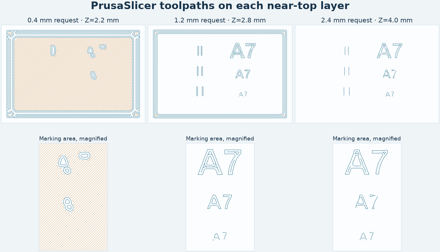
Blue lines show perimeter moves and amber lines show other model extrusion. Bottom panels magnify the same layers. Their heights are shown above, so a single slice is not treated as the finished surface.
At Z = 2.2 mm, the 0.4 mm depth case returned a mostly filled plate and only fragments around the intended letters in the close-up. The 1.2 mm case at Z = 2.8 mm showed recognizable 5.50 mm and 3.25 mm A7 outlines, with the 2.00 mm row reduced to thin paths. The deepest case at Z = 4.0 mm showed recognizable large letters, a less continuous middle-row 7 and fine single strokes in the smallest row. The selected layer with greater local rise can still have weaker strokes on individual characters.
| Requested carving depth | Model extrusion layers | Filament estimate | Slicer time estimate |
|---|---|---|---|
| 0.4 mm | 11 | 1,004.03 mm | 20m 09s |
| 1.2 mm | 15 | 1,083.59 mm | 21m 10s |
| 2.4 mm | 21 | 1,182.53 mm | 21m 41s |
Decide which letters need to read at the intended viewing distance, then check neighboring layers around each feature. The strokes in these screenshots come from planned extrusion. Surface finish, plastic spread and dimensional fit are checks for the physical print.
Cut and check the hanger hole separately
We chose the 2.4 mm copy for the hole because it gave the largest median rise on the 2.00 mm row. In Blender, a 96-sided cutter with 1.8 mm radius removed material at X = −17 mm and Y = 0. The center is 7 mm from the left edge of the plate. The exact Boolean result preserved the outside dimensions, with 352,430 triangles. A downward ray through the center found open space. At the midpoint of the backing, two orthogonal ray pairs measured 3.600 mm across the bore. Exact-position edge counting again reported zero boundary or overused edges.
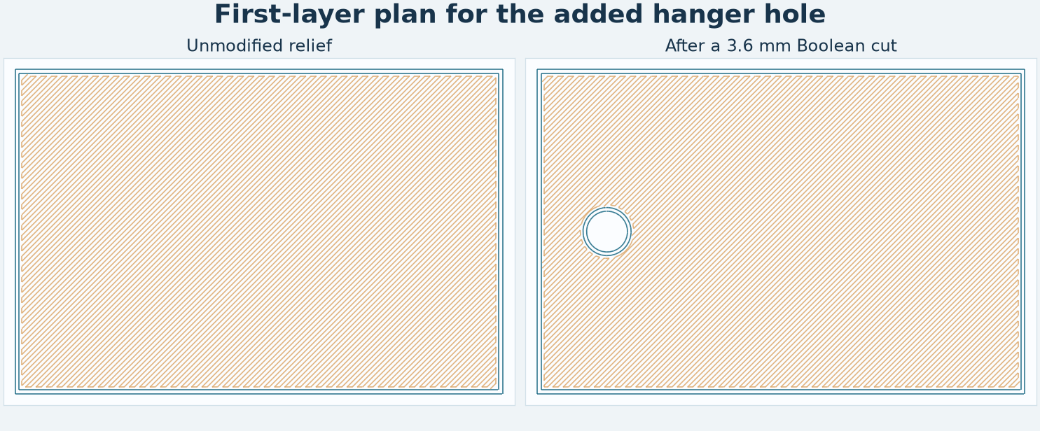
Both panels are Z = 0.2 mm in the same profile. After cutting, the slicer plans circular perimeter moves around the hole and keeps the surrounding base filled.
The cut copy still used 21 model-extrusion layers. The estimate rose from 21m 41s to 22m 28s with the extra perimeter work. The package to hand off is the checked STL and its matching slicing profile. Keep the editable mesh if the hanger hardware diameter or clearance changes. For a separate test of support paths on a sculpted shape, see the Rodin and Meshy STL comparison.
Frequently asked questions
Which depth would I start with?
For this source and profile, the 1.2 mm version gave clear large and medium paths in the inspected layer, with lower sliced height. The 2.4 mm version gave the strongest measured rise at the smallest lettering. If text is a serial number or a required identifier, change its design size and check all characters on the actual print.
Can I use the API’s GLB in a slicer?
The route returns both formats. We used the binary STL and checked its scale, surfaces and orientation before slicing. Use the GLB when a preview or pipeline needs its scene data.
Does this hole fit a 3.6 mm pin?
The digital bore measured 3.600 mm in the backing. The part and hardware dimensions after printing depend on fit and process tolerances. Use a measured test print to choose the allowance.
Found this useful? Share it