Rodin STL vs Meshy Relief for Photo-Based Printing in 2027
Compare freestanding Rodin and flat-backed Meshy STL outputs from the same image, with matched dimensions, cross-sections, mesh data and actual costs.
We sent the same image of a curved horn to Rodin 2.5 and Meshy Relief. Rodin returned a freestanding form with modeled thickness around the back. Meshy returned a raised carving on a rectangular plate. After setting both to the same 60 mm planar span, the Rodin mesh measured 15.361 mm along the chosen depth axis and the Meshy plaque measured 6.999 mm. A side view and sections through the original triangle geometry make the difference clearer than the front silhouette alone.
Key takeaway
- Rodin returned 50,000 triangles in a 2,500,084-byte STL for $0.48. Meshy returned 520,150 triangles in a 26,007,584-byte STL for $0.80.
- Meshy delivered a 60 mm long plate with a 1 mm back and almost 6 mm of raised geometry. We set Rodin’s comparable 60 mm span ourselves because the original STL carries no physical units.
- At 0.5 mm above the lowest point, the Meshy section outlines its rectangular plate. The Rodin section intersects only small portions of the rounded horn.
- Both original meshes had zero boundary edges in the exact-position check. The shape and intended orientation still need their own review before printing.
One picture, two different geometry requests
The input was Meshy’s public 629 × 642 PNG example of a curved, decorated horn. Its two tips point upward and the lower arc has bands and engraved detail. The background is transparent. We used the same original image URL for both jobs on November 14, 2026. Since the image only shows the front of the asset, it provides no reference geometry for the rear thickness of a freestanding part.
For Rodin 2.5 on SandBase, we requested the High tier, 50K Triangle, STL, no materials and seed 42. This job reconstructs a whole object from one image. For Meshy Relief on SandBase, we reused the exact High, 1 mm-base STL from our Meshy Relief depth and plate thickness test. That request used emboss mode, a flat base, 60 mm on the long side and mesh resolution 512. Carving depth was left at the preset’s default. Meshy documents a 6 mm default for this preset. Meshy Relief API documentation
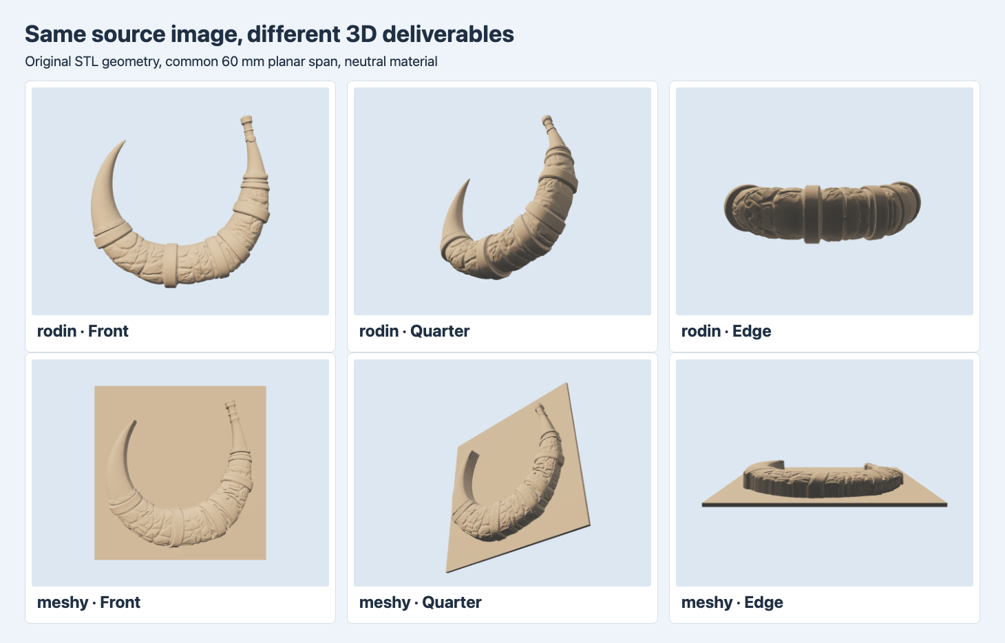
The meshes use a common neutral material, lighting, camera positions and a 60 mm planar span. Rodin was reoriented for comparison. Top row is Rodin, bottom row is Meshy.
Both front views make the curve and bands recognizable. The quarter view shows Rodin’s raised bands wrapping around a rounded form. In the Meshy export the horn protrudes from a plate, with a flat back and an abrupt rise at the contour. In the edge view the Rodin form has material around the depth axis, while the bottom of the Meshy file stays flat. Choose the route according to whether the design needs a part that can be viewed from multiple sides or an image raised from a panel.
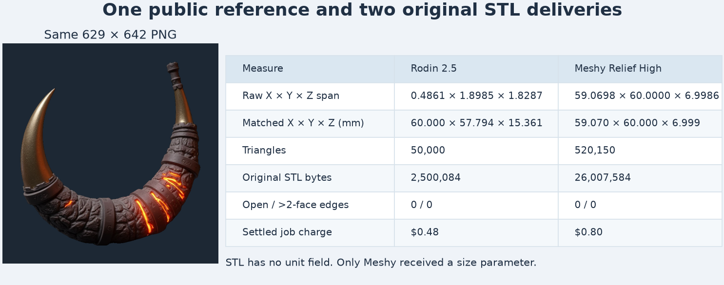
The native span is taken directly from vertices. The shared-span row uses a rotated and scaled Rodin copy and the original Meshy dimensions.
Read the original coordinates before choosing a print size
| Original file | Native X × Y × Z span | Triangles | STL bytes | Actual charge |
|---|---|---|---|---|
| Rodin 2.5 | 0.486052 × 1.898546 × 1.828737 coordinate units | 50,000 | 2,500,084 | $0.48 |
| Meshy Relief High | 59.070 × 60.000 × 6.999 in the requested mm convention | 520,150 | 26,007,584 | $0.80 |
Binary STL stores coordinates with no unit field. Meshy’s planar span matches the requested 60 mm, so we interpret that output in millimeters. The Rodin request did not set a physical size. A slicer that reads the unscaled Rodin coordinates as millimeters would display a maximum span under 2 mm. We kept the raw files intact, then prepared comparison copies. To bring the horn into the same viewing plane, we mapped Rodin’s source axes by setting display coordinates (X, Y, Z) to source coordinates (Y, Z, X), so the original thin X dimension became display Z. We multiplied all Rodin coordinates by approximately 31.6031 and left Meshy’s scale at one.
The resulting display envelopes are 60.000 × 57.794 × 15.361 mm for Rodin and 59.070 × 60.000 × 6.999 mm for Meshy. These are axis-aligned extents in the stated pose. The difference in the depth dimension is about 8.362 mm in this normalization. It is not a direct measurement of the original horn and it would change if you chose a different print size or orientation.
Both STL payloads fit the binary length formula of 84 bytes plus 50 bytes per triangle. That explains the large byte difference in these two original files. Each vertex position was grouped by exact coordinate before the topology count. Both gave zero edges used once, zero edges used more than twice and zero zero-area triangles. These checks cover specific edge and face properties. They do not test self-intersections, whether one contact patch holds the whole print down or whether the material is thick enough for a given process.
Compare depth through the same positions
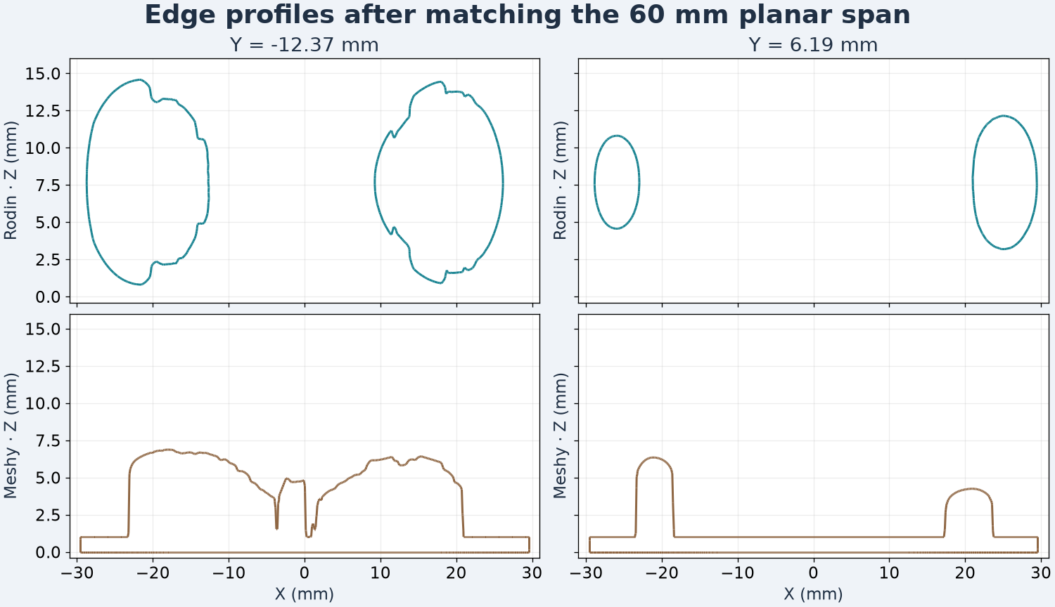
The outlines are intersections with planes at Y = −12.37 and 6.19 mm. Both models are centered in plan and their lowest point is at Z = 0.
At Y = −12.37 mm, Rodin’s cut reached Z = 14.571 mm, with a lowest intersected point at 0.798 mm. Meshy reached 6.867 mm there and the plate’s bottom was at zero. At Y = 6.19 mm, the Rodin intersection starts at 3.185 mm and rises to 12.141 mm. The Meshy section still reaches the bottom and tops out at 6.341 mm. These are measurements at two chosen positions, while the whole-mesh envelope includes points outside those slices.
The curved Rodin section shows why rotating a freeform model changes the areas that meet a print bed. It also shows the additional volume implied by reconstructing a complete form. The Meshy section is useful when fitting a part into a shallow opening because the plate sets a flat reference for measuring the raised surface. For a framed plaque, compare both the maximum height and the outline of the plate with the opening. For a freestanding piece, use the reference orientation to inspect the underside, tips and any section that needs to remain thick.
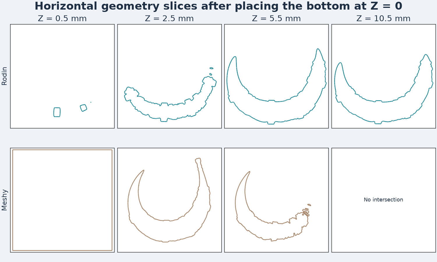
Each column slices both positioned meshes at the indicated Z. These plots show geometric intersections.
At Z = 0.5 mm, Meshy has a rectangular contour. Rodin has a much smaller intersection near the lower arc. By Z = 2.5 mm, both cut through the subject, with different outlines. The Rodin model still intersects the plane at 10.5 mm. The Meshy model ends below that level. These planes are held at the same height to compare the two assets. They do not provide measurements of print time or support material.
What an actual slicer produces
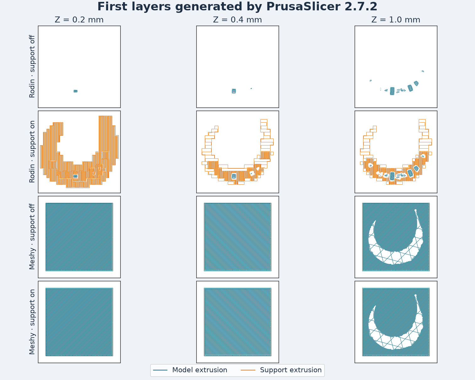
These paths come from the four generated G-code files. Teal indicates model extrusion and orange indicates support or interface extrusion. Travel, skirt and custom moves are hidden.
We sliced both positioned 60 mm copies in PrusaSlicer 2.7.2 with a generic profile, a 0.4 mm nozzle, 0.2 mm first and subsequent layers, two perimeters and 15% infill. We ran each model with automatic support off and on, leaving the support threshold and other settings at their defaults. The previews show the same three layer heights.
| Model and automatic support | Extrusion layers | Layers with support extrusion | Estimated time | Filament length |
|---|---|---|---|---|
| Rodin, off | 77 | 0 | 34m 08s | 1,831.73 mm |
| Rodin, on | 77 | 36 | 53m 36s | 2,910.71 mm |
| Meshy, off | 35 | 0 | 47m 58s | 2,120.10 mm |
| Meshy, on | 35 | 0 | 47m 58s | 2,120.10 mm |
The freestanding mesh has a small first-layer footprint in this orientation. With support enabled, the slicer added paths below both lifted ends. The plaque has a broad first-layer footprint and generated no support extrusion. It also took longer in the estimate than the unsupported freestanding job. Fewer layers can still take longer when each layer of the base covers a larger area. These are estimates from the generated files. The test did not send G-code to a printer, and orientation or a different profile may change the result.
Decide which shape fits the project
For a flat badge, plaque or panel, the base helps define an installation surface. The main dimensions to specify are the planar envelope, the remaining thickness behind the carving and the total height above the mounting face. Choose a relief depth that allows the small features to remain legible in the process you will use.
For a display prop, the side and rear matter in their own right. The opposite view can expose reconstructed folds, the shape of the tips, and wall thickness that you cannot check against the source image. Orient the part for its intended purpose, then inspect its print-bed contact and overhangs in a slicer. A manufacturing check would also use a known layer height, material and support strategy. The measurements here give a starting geometry for those checks.
Reproduce the test on your own subject
Use a single publicly reachable image for both requests. Save its hash, the two job IDs and the original STL downloads. The following example requests a 50,000-triangle Rodin STL from the same public source. Use a server-side bearer token with POST https://api.sandbase.ai/v1/run, then read the returned job via GET /v1/run/{id}. Calls can incur a charge.
{
  "model": "hyper3d/rodin/2.5/image-to-3d",
  "images": ["https://static.sandbase.ai/examples/meshy/relief/input_image_0.png"],
  "tier": "Gen-2.5-High",
  "geometry_file_format": "stl",
  "quality_mesh_option": "50K Triangle",
  "material": "None",
  "seed": 42
}
Check native axes and scale before importing a comparison copy. For a freeform object, note which side the photograph shows, and treat unseen surfaces as inferred. For an embossed object, measure the board, tallest relief and the height available inside its final frame. Both workflows benefit from a cross-section through the narrowest or most important detail. Keep any reorientation, scaling or repair separate from the original mesh when recording measurements. See the GLB, FBX, OBJ and STL round-trip test for examples of format-specific import checks.
The photo relief tag test compares three carving depths and the resulting letter paths on a smaller flat STL.
FAQ
Which output should I start with for a wall plaque?
Meshy Relief gave a flat base and controllable plate dimensions in this test. Rodin gave a complete curved object. Pick the one whose cross-section matches the intended assembly.
Do equal input images make this a quality benchmark?
The input was controlled, but the intended outputs and mesh settings differ. The measurements describe two deliveries from one photo and do not establish reconstruction accuracy or general print quality.
Did these parts physically print?
No physical print was made. The article documents original geometry, section previews and a PrusaSlicer estimate.
SandBase ran and billed the two jobs. Meshy uses the previously measured High result. Figures are based on the original STLs. The cover is illustrative.
Found this useful? Share it