MoGe-2 vs MoGe-3 for Single-Image Depth in 2027
Compare MoGe-2 and MoGe-3 on a calibrated Blender scene. See numeric PLY depth, native and held-out errors, actual fees, and visual depth maps.
MoGe-3 gave a lower raw depth error than MoGe-2 on our calibrated indoor scene. We then used one known patch of the wall to correct the scale. On the remaining pixels, MoGe-2 had a slightly lower mean absolute error. The result gives two distinct answers for a developer choosing a single-image geometry route. Raw metric depth and the relative shape left after a scale correction deserve their own measurements.
Key takeaway
- Both models received the same synthetic 640 × 480 RGB image and the camera’s known horizontal field of view, 54.432°. The reference depth came from Blender ray intersections.
- On 304,176 common pixels, MoGe-2 had a raw mean absolute error of 1.907 m and MoGe-3 had 1.605 m. Both underestimated depth in this scene.
- We fitted one multiplier per route on the same 18,200-pixel back-wall patch. On the other 285,976 common pixels, mean absolute errors were 0.105 m and 0.115 m respectively.
- Both jobs returned a GLB, a PLY point cloud and PNGs for depth preview, mask and normals. We measured numeric depth from PLY coordinates. Actual charges were $0.050 and $0.075.
- This test used one computer-rendered room and one run per route. It does not establish a wider accuracy ranking or calibrated measurement performance on real photos.
Build a scene with a known camera and depth
The input was an original Blender 4.5.9 Cycles render of a simple indoor scene. There are two walls, a floor, several boxes and a sphere. We placed the objects at distinct depths and used a camera with known intrinsics. The input was an ordinary RGB image. Each model received the image and its horizontal field of view. Neither received the depth reference or any object distance.
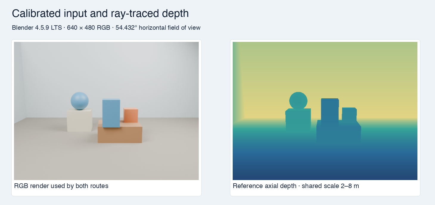
The left image was sent to both routes. The right panel visualizes the independent depth reference in meters on a shared 2–8 m scale.
For each of the 307,200 pixel centers, we cast a ray through the known camera and found the first surface intersection. We transformed each hit back to camera space and took forward axial depth. In this setup that quantity is the negative camera Z coordinate, in meters. A ray farther from the center may travel a greater distance to a surface with the same axial depth. Using the ray length as the target would change the comparison away from the image center. We also stored an object ID for each first hit so we could inspect errors separately on the floor, walls and props.
The render is a controlled fixture, with simple geometry and known camera pose. Real photographs may have unknown lenses, distortion, transparent surfaces or lighting that makes edges hard to see. The scene tests whether the two output files line up with a known depth field. Results on one room cannot estimate performance on a catalog of photos.
Read numeric depth from the returned point cloud
MoGe-2 ran the vitl-normal checkpoint. MoGe-3 ran with three refinement steps. Both used apply_mask: true, resolution_level: 9 and the same supplied fov_x. The schemas expose different controls. This tests the documented configurations with a common image and field of view. It does not separate the effect of MoGe-3 refinement from other version differences. Microsoft MoGe implementation and coordinate conventions
Each route returned a GLB, a PLY, and depth, mask and normal PNGs. Both GLBs passed the Khronos validator with zero errors and warnings. The color depth PNG is a preview. For measurements we used the PLY numeric positions. The exported clouds in this run use rightward X, upward Y and negative Z in front of the camera. We reprojected using the supplied intrinsics, took the pixel containing the projected center, and checked that the vertex RGB exactly matched the source at every mapped pixel. The maximum center offset was below 0.001 pixel for both exports. No model output was resized to force a correspondence.
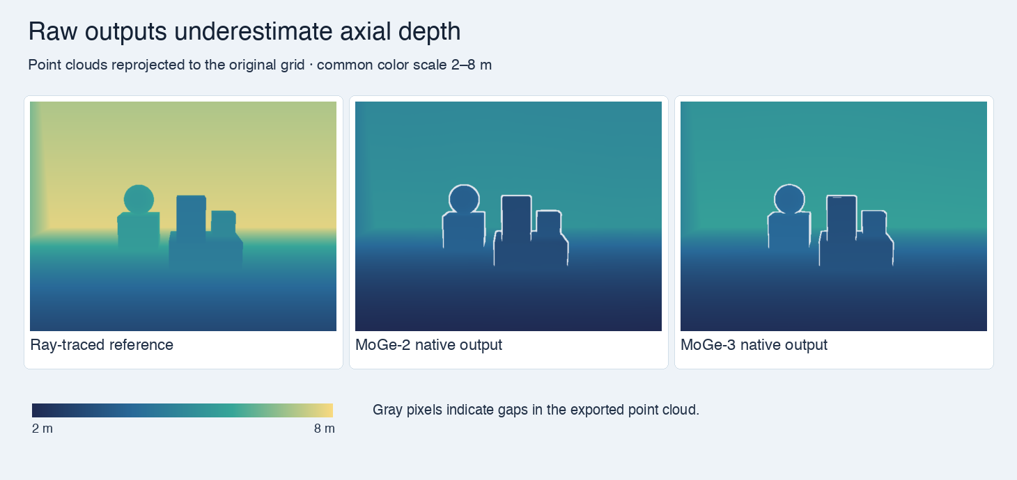
The same depth colors are used for every panel. Gray gaps indicate missing positions in the exported point clouds.
Both returned mask PNGs were all white, while the PLY files contained 304,334 and 304,565 vertices. A white mask pixel did not guarantee a point in these exports. The intersection of both projected clouds and the reference gave 304,176 pixels, or 99.02% of the image. Compare on the same pixel set so that a missing point cannot improve one route’s score by removing a difficult pixel from only its denominator. The article reports coverage and errors separately.
Compare raw depth before calibrating either model
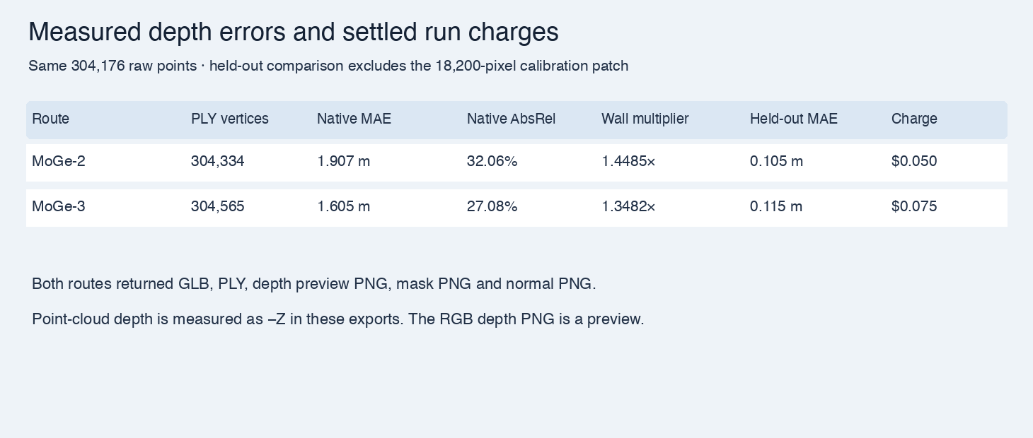
The native columns use the 304,176 common pixels. The held-out column excludes the wall patch used to fit the multiplier.
| Measure | MoGe-2 | MoGe-3 |
|---|---|---|
| PLY vertices | 304,334 | 304,565 |
| Raw mean absolute error | 1.907 m | 1.605 m |
| Raw RMSE | 1.963 m | 1.648 m |
| Raw mean absolute relative error | 32.06% | 27.08% |
| Raw median prediction / reference | 0.6899 | 0.7398 |
| Scale multiplier from the wall patch | 1.4485× | 1.3482× |
| Held-out MAE after wall calibration | 0.105 m | 0.115 m |
| Held-out median absolute error | 0.064 m | 0.063 m |
| Actual charge | $0.050 | $0.075 |
MoGe-3 reduced raw MAE by about 0.302 m in this scene. The median depth ratios show why the raw maps look nearer than the reference under a shared color scale. The reference median depth at the back wall was 7.464 m. MoGe-2 predicted a median of 5.175 m on the same wall pixels and MoGe-3 predicted 5.563 m. Both preserved the general foreground and background order, but neither recovered the scene’s actual scale.
MAE averages absolute depth errors in meters. RMSE weighs the larger errors more heavily. Mean absolute relative error divides each absolute error by the reference depth before averaging. A developer checking an expected installation distance may care most about meters, while a depth ordering task can start from relative spacing and edge placement.
Calibrate with one wall patch and test the rest
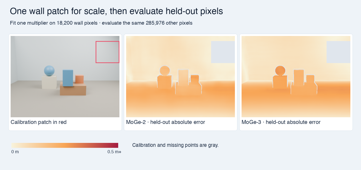
The red rectangle marks the 18,200-pixel patch used for scale. Both error panels use the same color scale. Missing positions and the calibration patch are excluded.
We computed a single scale factor for each model as the median of reference depth divided by predicted depth on the patch. We then applied that factor to the predictions for the other 285,976 common pixels. That kept evaluation pixels outside the fit. The reference is only from the same scene, so the holdout tests transfer across this view. It does not test transfer to a different room or camera.
After correction, MoGe-2 had the lower held-out MAE, by roughly one centimeter. MoGe-3 had a slightly lower held-out median absolute error. The metrics capture different parts of the error distribution, and the ranking depends on which quantity a pipeline cares about. Both still show residuals in the floor and prop regions. Multiplying all depths corrects one scale factor. It cannot independently fix a local shape or discontinuity.
Choose the check your pipeline needs
| Use case | What to record |
|---|---|
| Compare uncalibrated output against a known scene | Shared-pixel coverage, raw MAE, bias, and camera settings. |
| Apply a known scale reference | The calibration region, multiplier and separate held-out error. |
| Use the mesh in a 3D viewer | The original GLB, geometry orientation, bounds and relevant surface gaps. |
| Diagnose depth from images | Point-cloud coordinates, projection checks and original masks as separate inputs. |
To repeat the experiment, make or capture a scene with a known field of view and a measured depth reference. Submit the same image URL to both SandBase routes. Preserve each returned PLY and record its coordinate convention before comparing. If the eventual deliverable is a full object mesh from an image, add a separate backside or multi-view check. A camera-facing depth field only covers what that image can see. Compare full-frame and object-selected 3D assets
Preserve the request and the comparable denominator
Use the following MoGe-2 request shape with your reachable RGB image. Submit to POST https://api.sandbase.ai/v1/run with a server-side bearer token, save the run ID, and poll GET /v1/run/{id}. For the tested MoGe-3 configuration, use microsoft/moge-3 and replace the checkpoint field with "num_refinement_steps": 3.
{
  "model": "microsoft/moge-2",
  "image": "https://example.com/your-calibrated-image.png",
  "fov_x": 54.432223114614956,
  "apply_mask": true,
  "resolution_level": 9,
  "checkpoint": "vitl-normal"
}
The image URL is a placeholder. Use the horizontal angle from your own calibrated camera. Before running the comparison, decide how to handle pixels missing from one point cloud. Report the coverage alongside the common-pixel metrics so the error cannot be read as a score over the whole image. If your application needs edge depth, report results around object boundaries as a separate group and preserve a picture of the gaps.
The MoGe-3 calibration guide checks the camera field of view and a known-width scale anchor on a separate scene.
FAQ
Is the RGB depth PNG an array of distances?
The PNGs received in these jobs are RGB previews. This comparison uses numeric PLY positions and explicit camera reprojection for depth.
Does supplying the field of view fix scale?
It fixes the projection angle used in the request. In this scene both raw outputs underestimated depth despite receiving the same known field of view.
Should I always prefer MoGe-3?
MoGe-3 had lower raw mean error on this fixture. After one-patch calibration MoGe-2 had slightly lower held-out MAE, while MoGe-3 had a slightly lower held-out median. Test with the metric and image mix that match your task.
Found this useful? Share it