Checking Field of View and Scale in MoGe-3
Three MoGe-3 point clouds from the same image compare estimated and supplied field of view, metric depth error, and a known-width scale check.
MoGe-3 correctly ordered three blocks from near to far in a single rendered image. Its default camera estimate was 57.02°, close to the true 58.72°. The native near-and-far depth error was still 0.616 m on average. Scaling that result with a known 0.300 m strip reduced the error to 0.138 m. With a deliberately wrong 42° input, the same width correction made the depth estimate worse. The point cloud helps diagnose what changed when all you have is one image.
Key takeaway
- We sent one image through the MoGe-3 endpoint with no FoV, with its true horizontal FoV, and with an intentionally too-narrow 42° FoV. Each completed at $0.075, for $0.225 total.
- The point clouds encoded 57.02°, 58.72° and 42.00°, recovered by projecting their coordinates back to image pixels. The true-angle output still had a native mean absolute error of 0.720 m on the two held-out fronts.
- Width scaling cut mean absolute error on the separate near and far fronts from 0.616 to 0.138 m for the automatic result, and from 0.720 to 0.194 m for true FoV. The 42° case went from 0.988 to 1.752 m.
- The true far-to-near depth ratio was 1.783. The three predicted ratios were 1.961, 2.011 and 1.545. One uniform scale cannot change any of those ratios.
Give the test a dimension it can check
We built three plain blocks in Blender at known distances, using meter units. A 640 × 480 render shows the near orange block, a taller blue middle block with a strip, and a pale far block. The blocks’ front planes have axial depths of 2.690, 3.720 and 4.795 m. The strip is 0.300 m wide and its backing face sits at 3.712 m. The 32 mm camera lens with a 36 mm horizontal sensor produces a 58.7155° horizontal field of view on this uncropped render.
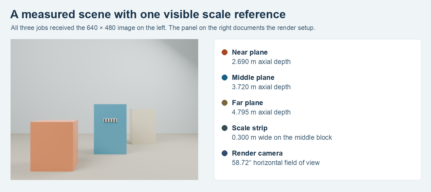
The picture on the left is the image used for the jobs. The labels and lengths on the right came from the authored scene and were only used during evaluation.
The same PNG went into all three jobs on November 14, 2026 UTC. We held resolution_level: 9, num_refinement_steps: 3 and apply_mask: false constant. The automatic request omitted fov_x. The other two passed 58.7155° and 42° respectively. The model did not receive the strip width, a distance reading or a scene file. For the comparison, we cast a ray through each pixel in the Blender scene and took the first hit’s axial depth. This is the distance along the camera’s viewing axis, which differs from the length of an oblique ray to that surface.
The Microsoft MoGe-3 research page describes metric point maps from one view. Here we measure the files from the SandBase integration on one synthetic still life. The exercise tests whether a known camera angle and one scale anchor help on that image. All geometry checks use surfaces visible from the rendered camera.
Use the point cloud for numeric depth
Each response included a GLB and file fields for a PLY point cloud, depth PNG, normal PNG and validity-mask PNG. All three GLBs passed the glTF validator with zero errors and warnings; their original files were between 17,122,808 and 17,173,180 bytes. All PNGs were 640 × 480. A depth preview makes it easy to find a surface, but a color in the PNG is not the meter depth used below. We took camera-space coordinates from the original PLY files.
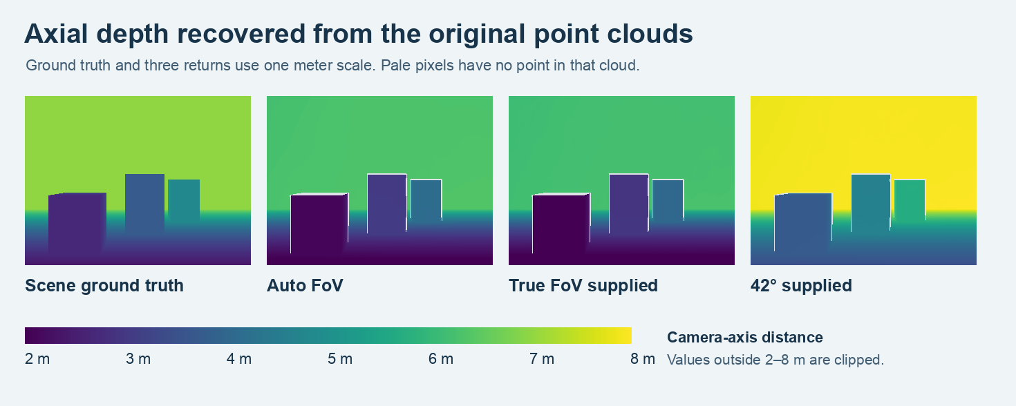
Point coordinates were projected back to their image positions before converting depth to color. All four panels use the same 2–8 m scale. Pale gaps in returned rasters are pixels that lacked a point.
The projected slopes X/Z and Y/Z of the points fell along a regular pixel grid. We recovered both focal lengths from that spacing, used the centered image principal point, and validated each recovered pixel with the original RGB from the input. Across the three clouds the largest remaining offset from a pixel center was below 0.00011 pixels. The relation FoV = 2 × atan(image_width / (2 × focal_x)) gave the horizontal angle in the geometry. In this case it recovers the supplied value on requests with an explicit angle.
Even with apply_mask: false and three entirely white returned mask images, the PLYs had 303,255, 303,241 and 304,134 points out of 307,200 possible pixels. The error comparisons use 303,241 pixels present in every return and in the scene truth. The numeric check relies on actual projected points. Check coverage from the projected PLY when a particular coordinate is needed.
Measure the ratio before any scale correction
| FoV request | Recovered FoV | Near median | Middle median | Far median | Far-to-near ratio |
|---|---|---|---|---|---|
| Blender truth | 58.72° | 2.690 m | 3.720 m | 4.795 m | 1.783 |
| Auto | 57.02° | 2.098 m | 3.035 m | 4.115 m | 1.961 |
| True horizontal FoV | 58.72° | 1.995 m | 2.931 m | 4.012 m | 2.011 |
| 42° test | 42.00° | 3.702 m | 4.639 m | 5.719 m | 1.545 |
All three placed the fronts in the intended order. The median depths differ from truth at each plane. For example, giving the correct angle made the projected rays match the render angle but the near front was still about 0.695 m too close. The ratio divides the farther depth by the nearer one. Both values change by the same factor under uniform scaling. A metric asset that needs both distances to be accurate should check at least two actual reference locations.
Fit the strip once and check different surfaces
We measured a span of 45.977 pixels across the authored strip using the known projection. At each run’s median strip depth, we estimated its width as pixel span times axial depth divided by the inferred horizontal focal length. The estimate assumes a fronto-parallel strip. We used a single multiplier, true width divided by predicted width, to scale the cloud. Only 552 pixels on the strip and marker were used to estimate its median depth. The test set comprises 33,871 common pixels on the separate near and far front planes.
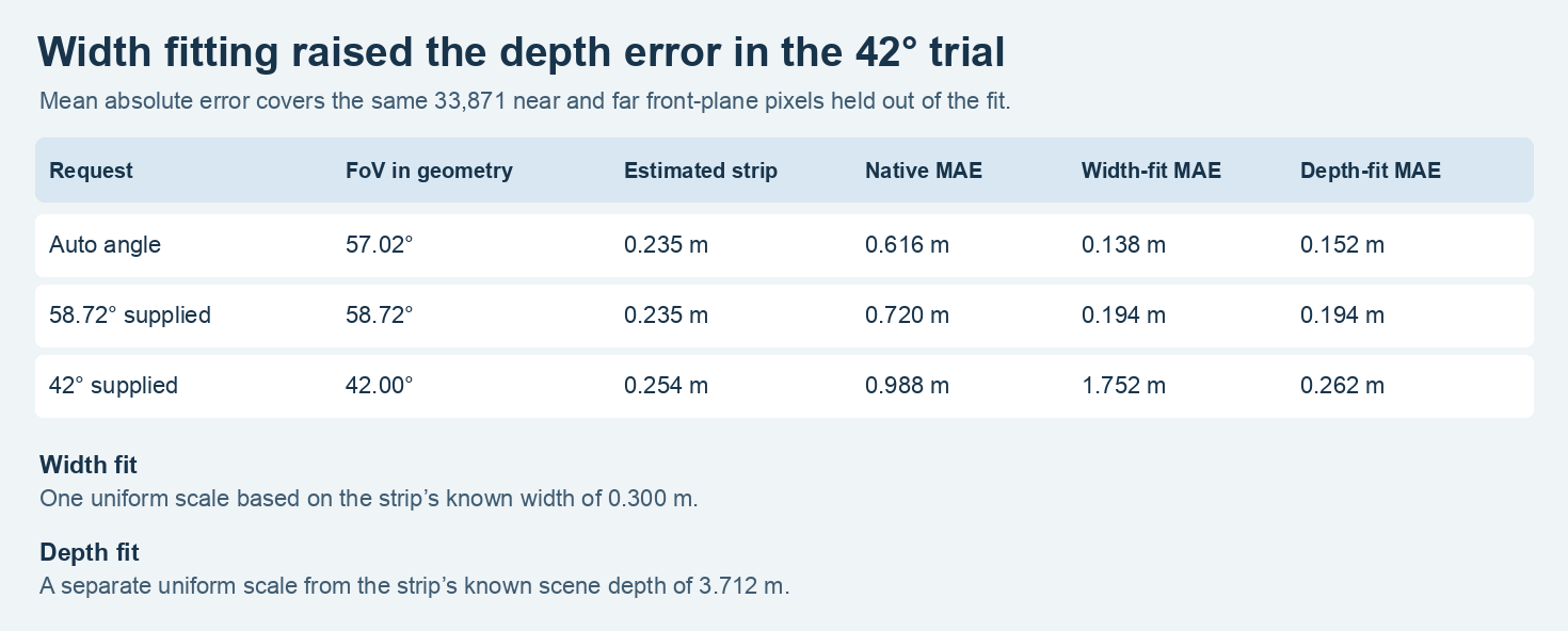
The width fit knows only the strip’s width. The depth fit is a separate calculation that uses its true scene distance. Lower mean absolute error on the held-out near and far fronts indicates closer axial depth for these pixels.
The automatic and true-angle results both estimated the strip width at roughly 0.235 m. Width scaling by about 1.277 reduced their held-out errors. The 42° case gave a width of 0.254 m, closer to 0.300 m than the other raw widths. Its predicted fronts were already too far from the camera. Scaling it up to match the strip pushed those surfaces away and worsened the error by about 0.765 m. One width is enough to fit one scalar. It cannot change the angles of the projected rays or guarantee the correct depth scale for the whole image.
For a second check we used the strip’s known depth of 3.712 m instead of its width. In the wrong-angle case, that reduced held-out error to 0.262 m. This changed the size of the whole cloud, while the far-to-near ratio stayed at 1.545. The test shows why it is worth recording what was used for scale and keeping another measurement for verification. The earlier MoGe-2 vs MoGe-3 comparison controls the camera and compares two model versions on a different scene.
Report the error on each object you will measure
A single average can look better because the closest object covers most of the image. The near face contributed 24,372 sample pixels, about 72% of the held-out comparisons here. After width fitting, the automatic result put its median near depth at 2.680 m, just 0.010 m closer than the reference. The far median became 5.256 m, leaving it about 0.461 m too far away. With true FoV and the same width fit, the medians moved to 2.548 m and 5.125 m. That order gives a smaller far error and a larger near error on this scene.
When checking a measurement workflow, keep the per-object error next to the combined pixel error. Save the image dimensions, supplied and recovered FoV, actual scale anchor and the regions used for verification. A buyer comparing different product areas can then check the feature at its own distance, rather than relying on error averaged across a scene.
Frequently asked questions
Can I use the lens angle from my camera specifications?
Use the horizontal angle for the image actually submitted. Cropping changes what spans the image, including whether its center corresponds to the optical center. Our test used the complete render and a centered projection. When you have a calibrated image, keep the focal length, crop and units with the measurement record.
Should I measure the PNG or the GLB?
The depth PNG is helpful for reviewing edges and relative separation. For the numbers above we projected the PLY to the exact input pixels and checked the scene units. Inspect the GLB when importing a mesh and use a separately controlled reference to validate dimensions.
Does scaling one marker tell me the size of the back of an object?
It changes the scale of the visible reconstruction. It provides no additional observation of an occluded surface. Take another view or make a separate physical measurement if the hidden part matters.
Found this useful? Share it