Build an Interactive Exploded View from an AI 3D Mesh
Build a Three.js exploded view of an AI tool chest. Compare original and corrected latches, preserve assembled transforms and test an interactive demo.
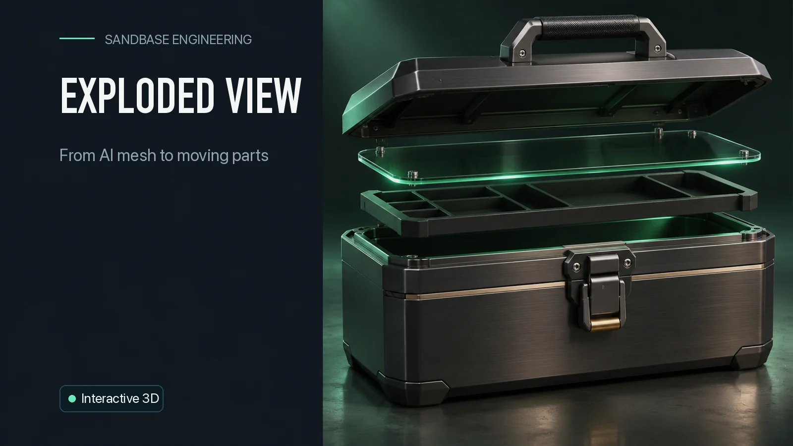
The first time we pulled the tool chest apart, the orange latch took a strip of the front trim with it. The original Hi3D mesh gave us a selectable object, but the latch and trim were fused into that selection. Two cuts across the long dimension of the trim gave the viewer a separate latch and left 142 triangles of outer trim fixed in the assembled position. This walkthrough turns that tested correction into an interactive Three.js exploded view with a distance slider, a latch tilt control and a reset.
Open the interactive tool chest. Try the three assets in the selector. To see the difference most clearly, isolate the latch and use the same tilt angle on both Hi3D versions.
Key takeaway
- Give the intended moving part a reviewed ID. In this chest, Hi3D’s
part_6_primitive0and Tripo’stripo_part_10identify the closest corresponding pieces. - Save the assembled transforms before adding pivots. The tested Three.js reparenting kept every element of the assembled mesh matrices within about 2 × 10⁻¹⁷ on the three demo files.
- Fix the geometry selection before tuning the animation. The original Hi3D latch had 1,056 triangles. The edited piece has 974, and 142 triangles of outer trim stay fixed. Cutting crossing triangles increased the combined count by 60.
- Use the slider to inspect the starting state, midway clearances and the fully exploded state. The demo has surface patches and schematic movement. It provides no mechanical clearance or internal assembly guarantee.
Choose the part by motion
We reused the tool-chest exports from Tripo Segment and Hi3D Split on the same props. The chest GLB was the input to both routes. The existing Tripo Segment call settled at $0.48, and the Hi3D Split call at $0.40. We performed the repair and viewer test on November 14, 2026 UTC, using those existing files. No additional generation call was required.
Start with the visual task. On this chest, the user should be able to move the front latch away from the trim, isolate it and tilt the piece. The source exports called those nodes part_6_primitive0 and tripo_part_10. Those names are useful lookup keys for these files. They have no shared meaning across routes or across different jobs. Save a stable authored ID, such as front-latch, beside the raw node name. Version the map against the file hash so another upload cannot silently move the wrong piece.
The unedited Hi3D chest has 30 mesh objects and Tripo has 24. A segmentation object can be a flap of the shell, a side plate, or an area that includes neighboring detail. We apply a plain diagnostic color to the shell and a contrasting orange to the selected latch. The distinction keeps the moving geometry identifiable while the camera or part rotates. The viewer uses flat diagnostic materials on the three derived display files.
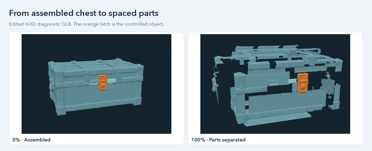
The two frames use the edited Hi3D demo file and the same camera. Orange identifies the latch. The lighter strip beside it stays in the assembled position as the other pieces move.
Repair the stretch of trim that follows the latch
In the Hi3D result, the clasp and a span of trim share one connected mesh object. Moving that node shows a long strip extending to either side of the hardware. Splitting by existing connected islands would not separate it. We used the width of the independently isolated Tripo latch as a reference and added 0.006 source units of margin on both sides. In the two files tested, the selected surfaces are aligned in the same asset axes. The lateral direction is asset Z. The clipping planes landed at approximately −0.05064 and +0.05712 in that coordinate space.
The script clips each triangle against the pair of planes. The polygon between the planes stays with the moving latch; the two outer regions go into a new node called trim-retained. It interpolates UVs linearly and renormalizes interpolated normals. A face crossing a cut line can become a polygon with extra corners and then several triangles. That is why 1,056 original faces become 974 moving and 142 fixed. Both the inherited transform and source positions on the remaining regions are preserved. The cuts are specific to the tool chest and a small leftover triangle-shaped projection is still visible on the edited latch.
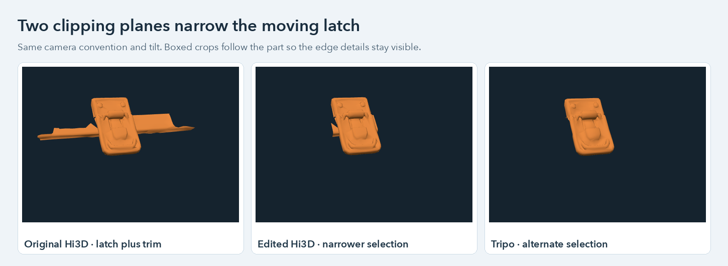
The panels show the original node, the edited Hi3D latch and the Tripo reference, isolated at 45°. The center still includes a small adjacent remnant. It no longer carries the long outer strips.
The trim released from the selection remains visible and has zero translation at full explosion. It is not removed from the model. Keeping it gives the assembled scene a place to return to and leaves a clear target for subsequent cleanup. In a production model, inspect the cut seam and whether the trim is meant to travel with a particular shell piece. A fixed trim node is the demonstration choice here. The cut was not capped.
| Browser GLB | Mesh objects | Selected latch triangles | Total triangles | File bytes |
|---|---|---|---|---|
| Hi3D diagnostic original cut | 30 | 1,056 | 34,662 | 999,200 |
| Hi3D diagnostic edited cut | 31 | 974 | 34,722 | 1,050,728 |
| Tripo diagnostic reference | 24 | 878 | 34,650 | 767,664 |
These are the actual diagnostic files served with the viewer. We stripped material and texture payloads from the local demo copies and retained positions, normals, hierarchy and part names. The original Hi3D selection came from a 4,600,960-byte export, and the original Tripo file was 1,781,448 bytes. Do not compare those original delivery bytes with a screenshot-based time estimate. Our sizes reflect the files before any HTTP transfer compression. All three demo GLBs validated with zero errors and zero warnings.
Add a pivot without snapping the part
Before moving anything, let the GLB root update its world matrices. Read each mesh’s bounds in the assembled scene. Place an empty group at the part anchor and use Three.js Object3D.attach to move the mesh inside the group while preserving the world transform. For the latch, the anchor is the lower Y edge at the X/Z midpoint of the assembled bounds. Use the mesh center for radial shell offsets. The demo adds the global centering and uniform scale one level above that assembly.
assembly.updateMatrixWorld(true);
const box = new THREE.Box3().setFromObject(latchMesh);
const pivot = new THREE.Group();
pivot.position.copy(box.getCenter(new THREE.Vector3()));
pivot.position.y = box.min.y;
assembly.add(pivot);
pivot.updateMatrixWorld(true);
pivot.attach(latchMesh);

const rest = pivot.position.clone();
const outward = new THREE.Vector3(1, 0.23, 0).normalize();
function setLatch(amount, radians, longestSide) {
  pivot.position.copy(rest).addScaledVector(
    outward, amount * 0.43 * longestSide,
  );
  pivot.rotation.z = radians;
}
This example assumes the assembly is untransformed while the anchors are computed, as in the demo. For an assembly already placed in a scene, convert world points into assembly-local coordinates before using them as child positions. Three.js warns that attach does not support a graph with non-uniformly scaled ancestors. Bake those transforms first or use an explicit transform conversion and verify the results.
At full distance the latch offsets by 43% of the assembled longest side in the positive X and slightly positive Y direction, in this sample. Shell fragments offset by 19% radially. The retained trim has no offset. The tilt reaches ±45° around the chosen local Z axis. That axis lets you visually test the selection and pivot. An actual hinge would come from a physical reference or part design, with the movement path checked against its neighbors.
Make the controls reproducible
We calculate each position from its stored rest value on every update. A scrub back to zero can use exactly the same values as the initial state. Playing the demo eases over 900 ms in either direction. Reset restores assembled positions, clears the tilt, reveals the other parts and returns the camera to its default angle. Range inputs also work directly without playing an animation. Opening the isolated latch moves the camera closer, so the neighboring geometry is easy to inspect.
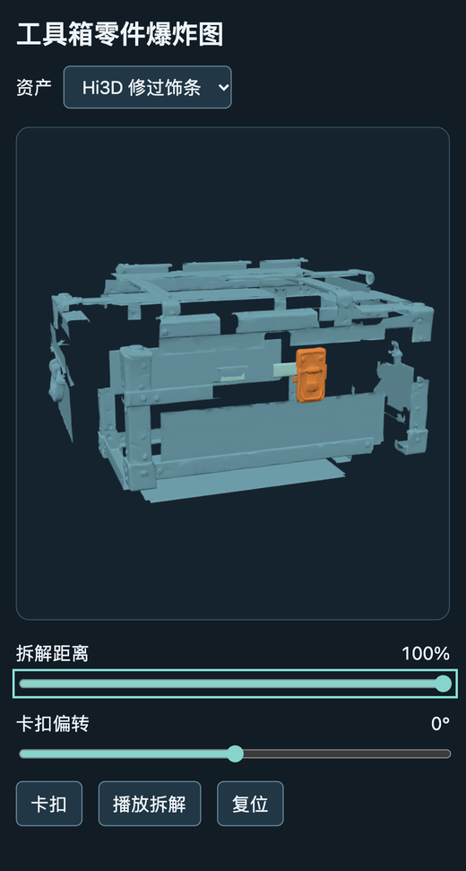
The local Chromium mobile viewport shows the 100% state and separate tilt, isolate, play and reset controls. The article uses a real browser frame captured from the demo.
We verified loading, the assembled state, slider endpoints, isolated 45-degree tilt, animation playback and reset in Chromium, including a mobile viewport. This is an interaction test. For a product launch, check the actual reader devices and CDN. Keep a static assembled image if the WebGL viewer is unavailable. Verify collisions, thickness and tolerances separately if the model goes from a page to a real assembly. See the generated GLB QA checklist for other preflight checks.
Reproduce the repair and viewer locally
The runnable source and the two source mesh files include the mesh edit, diagnostic export and test harness. Use Node.js 22, npm, unzip, and a browser with WebGL. Chrome is needed for the supplied automation. The source pack contains assets generated for this article series. It contains no API credentials and the steps below make no generation calls.
1. Extract the example and install the tested libraries
unzip exploded-view-source.zip
cd tool-chest-source
npm install --no-save [email protected] @gltf-transform/[email protected] \
  @gltf-transform/[email protected] [email protected] \
  [email protected]
The extracted directory contains both source GLBs and the scripts. If npm reports an engine mismatch, switch to Node 22 before installing.
2. Apply both cut planes and check their output
node trim-latch.mjs && node -e 'const r=require("./trim-report.json"); if(r.originalCount!==1056||r.segments[0].triangles!==974||r.segments[1].triangles!==142)process.exit(1); console.table(r.segments)'A successful run prints the 974 moving and 142 fixed triangles. The clipping script checks the world-axis assumptions before making a cut. If the axes differ, inspect the new asset’s transform and remeasure the interval before reusing the recipe.
3. Write and verify three diagnostic GLBs
node prepare-demo.mjs && node -e 'const r=require("./demo-glbs.json"); if(r.length!==3||r.some(f=>f.errors||f.warnings))process.exit(1); console.table(r.map(({file,bytes,triangles})=>({file,bytes,triangles})))'Each result appears in the demo directory. The report prints the three file sizes and counts in the table above. Check its errors before moving any GLB into your public directory.
4. Run the viewer with a local HTTP origin
node --input-type=module -e 'import {createPreviewServer} from "./server.mjs"; createPreviewServer().listen(4173,"127.0.0.1",()=>console.log("http://127.0.0.1:4173/"));'Open the printed address. Select each asset and move the slider. If a GLB is missing, the viewer displays a load error and leaves the movement controls disabled. Make sure the demo directory is beside the script and reload.
5. Exercise the controls with Chromium
node test-preview.mjs && node -e 'const r=require("./preview-checks.json"); if(r.length!==4||r.some(v=>!v.playbackBothDirections))process.exit(1); console.table(r.map(({mode,mobile,out})=>({mode,mobile,moved:out.latchOffset,fixed:out.trimOffset})))'The script starts its own local server. It produces screenshot files and four desktop or mobile test records. The edited variant should have a latch offset of about 0.43 asset units, with a fixed trim offset of zero. If Playwright cannot find Chrome, install Chrome from its official site before rerunning the test.
Frequently asked questions
Can an AI split give me an accurate hinge automatically?
The segmentation supplies mesh objects. Our outputs did not establish hinge coordinates. We moved the pivot to a visible bounding-box edge as a design choice for this viewer. Animate one part slowly through the intended path and use calibrated reference geometry when the hinge location matters.
Does the higher mesh count mean the repaired result has more detail?
The extra object keeps the detached span of trim in the assembled model. The additional faces come from splitting triangles across two cut planes. They describe the same sampled surface more finely near the cut.
Which source should I keep after the demo is working?
Save the original GLB, the edited GLB and the viewer’s per-part mapping. Use the original to check whether another cut is needed and the edited file to reproduce the working viewer.
Found this useful? Share it