Hi3D 3.0 Single vs Multi-View for Occluded Objects
Five Hi3D 3.0 geometries show what a front, side or rear input contributes to a hidden connector, rear vent and overall case shape.
Hi3D 3.0 built a plausible rectangular instrument from one front image. Its rear connector was practically flat. We kept the front image fixed and compared five sets of input views. Front plus rear made part of the connector rise above the case. Front plus left gave a lower average error across the entire back, while its connector stayed below the same local height threshold. The two-image choice depends on which surface must be right.
Key takeaway
- The front-only export had no raised connector samples at the tested threshold. Front plus rear matched 42 of the reference’s 308 raised samples. All four views matched 206.
- Using two inputs, front plus left gave 4.31% mean rear depth error and front plus rear gave 9.42%. Within the connector region the rear-view pair had the lower error, 5.91% versus 8.46%.
- The four-view run gave the lowest front, rear, left and right depth error among these five exports. Its connector region still had 1.80% mean error and its high relief covered only 66.88% of the reference mask.
- For an occluded attachment point, evaluate a local 3D measurement alongside whole-view shape. Include a direct view of the feature when that geometry matters in the final asset.
Change the view set and hold the generation settings
The authored fixture is a box-shaped device with a top handle, four feet, three front controls, a vent on the back and a round rear connector. We rendered the same mesh from the front, left, right and back with orthographic cameras. The orange rear connector is hidden in the front image. Its side silhouette can be seen in the two profile views. The rear image shows where it sits on the panel and how it relates to the vent.
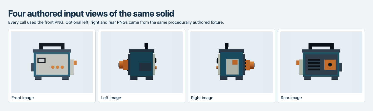
Every request used the same front PNG. The profile images show the connector projecting behind the body. The rear image shows its position next to the vent.
We used Hi3D 3.0 Image to 3D for the single front and Hi3D 3.0 Multi-View to 3D for four multi-image setups. Both used the documented 2048quality tier, face_count: 100000, GLB export, and texture and PBR disabled. The route offers no exposed seed in this comparison. We made the single-front and front-plus-rear calls together. The remaining three GLBs came from the same-fixture multi-view API evaluation and rear capture checklist, using the same PNGs in the same slots and the same shared settings.
| Route and view set | Original GLB triangles | Original bytes | Settled charge |
|---|---|---|---|
| Single front | 97,674 | 1,772,856 | $2.16 |
| Front + left | 97,172 | 1,766,640 | $2.16 |
| Front + rear | 96,520 | 1,759,824 | $2.16 |
| Front + both sides | 97,490 | 1,770,652 | $2.16 |
| Front + both sides + rear | 97,278 | 1,768,108 | $2.16 |
All five completed on November 14–15, 2026 UTC. The two new jobs cost $4.32; the five observed bills total $10.80 across the three studies. All original GLBs passed glTF validation with zero errors and zero warnings. The front-plus-rear export contains 18 repeated index triples when winding order is ignored, matching the 18-triangle difference between its original file count and its Blender 4.5.9 import count. The table gives the original file counts. The ray test uses the imported surfaces.
Start with the visible face and then turn the model
We centered each bounding box and divided positions by its longest dimension. A comparison against the front reference selected the best yaw among four quarter-turns. Every file kept its original yaw. We cast 128 × 128 orthographic rays per view. Mean absolute depth error measures the first-hit position difference where both the reference and export had a hit. It is expressed as a percentage of the longest normalized side. Positions missing in either shape are reflected in the silhouette intersection-over-union measure, separately from depth.
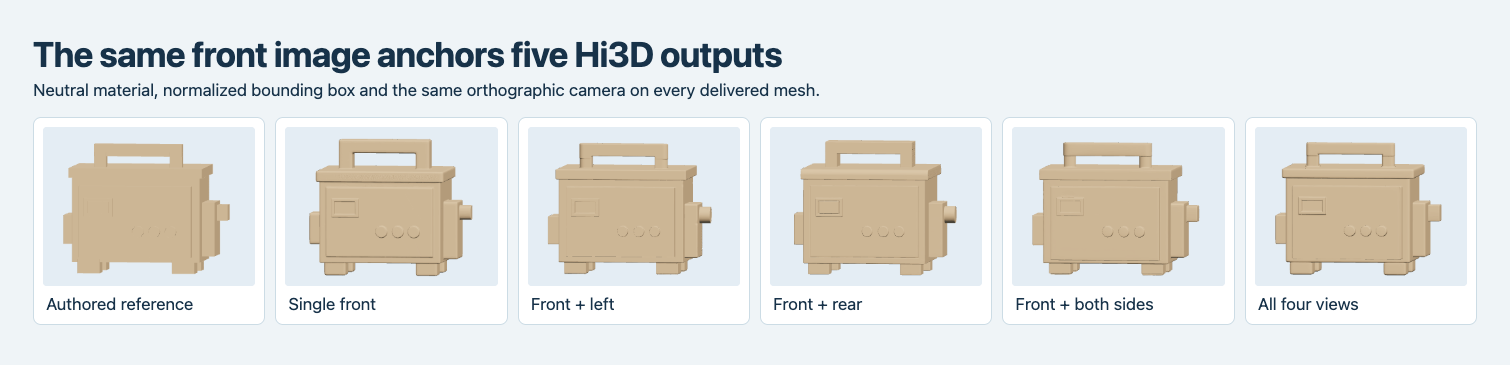
The visible front keeps the same screen and control arrangement in all exports. The matched front depth measurements still vary.
| View set | Front depth error | Rear depth error | Left depth error | Right depth error |
|---|---|---|---|---|
| Single front | 8.68% | 10.79% | 3.86% | 5.69% |
| Front + left | 2.50% | 4.31% | 3.30% | 4.45% |
| Front + rear | 4.37% | 9.42% | 3.68% | 4.01% |
| Front + both sides | 1.29% | 4.47% | 3.66% | 3.32% |
| Front + both sides + rear | 0.81% | 1.19% | 1.17% | 1.55% |
The two-view outputs tell different stories. The sample with the side input matched more of the broad rear plane by depth, even though the camera never looked straight at that plane. The sample with the rear input produced a recognizable vent and a local raised feature. With the same front input and two images in both cases, shape on the hidden surface can depend on what the extra view actually exposes. Scene size was normalized for this test, so these percentages describe relative geometry.
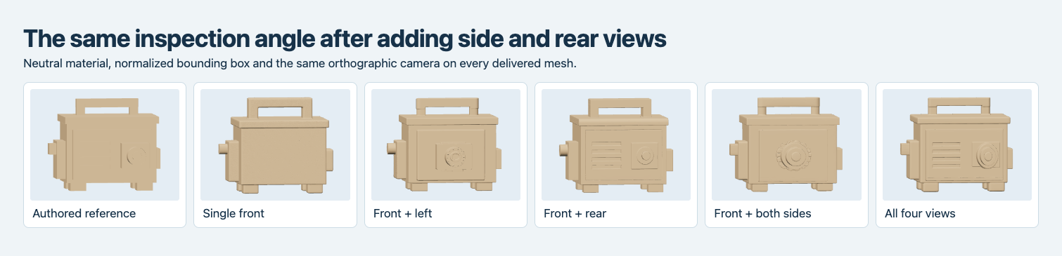
From the rear, the front-only result is nearly featureless. Front plus left and front plus both sides suggest a connector shape, while the rear view produces a clearer vent and connector in the tested exports.
Measure the connector above its own panel
We defined two rectangular regions on the authored rear grid, one around the vent and one around the connector. We also set a nearby strip between them to estimate panel depth separately for each model. A sample counts as raised when it stands at least 8% of the longest side above that model’s median panel depth. This relative measurement helps distinguish a connector with a short protrusion from an entire rear plane displaced along the depth axis.
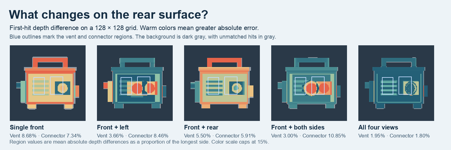
The warm colors mark larger depth errors. A run can fit the broad panel while missing the connector capture in the marked window.
| View set | Vent region depth error | Connector region depth error | Reference raised samples matched |
|---|---|---|---|
| Single front | 8.68% | 7.34% | 0 / 308 |
| Front + left | 3.66% | 8.46% | 0 / 308 |
| Front + rear | 5.50% | 5.91% | 42 / 308 |
| Front + both sides | 3.00% | 10.85% | 0 / 308 |
| Front + both sides + rear | 1.95% | 1.80% | 206 / 308 |
The side-only additions can make connector-like relief visible without reaching this height criterion in the authored connector window. The front-plus-rear model’s 95th-percentile connector relief reached 8.67% of the longest side. The four-view sample reached 21.63% and the authored reference reached 20.67%. Even though those last two heights are close, they cover different projected areas. The four-view output covers 206 of 308 raised reference samples with no raised hits outside the reference mask within the region. A single maximum height or recognition from a screenshot cannot establish that the whole mounting shape matches.
Choose the additional view by the part you need
If two input slots are all you can prepare, decide whether the recipient needs a plausible outer shape or a particular rear feature. Here the side pair did better on average rear depth, and the rear pair captured some of the connector’s relief. Collect side profiles and the rear together if case thickness and that hidden mounting surface must both be close. A production fixture should set its own millimeter tolerances after physical calibration, along with expected part location and reveal angle.
The images were rendered from one rigid authored fixture. We ran once per setup and compared two endpoint variants. The results are useful for choosing the next view to test on a similar case. The design leaves camera exposure, textured output, real photo capture and repeated-run variability outside the measured scope.
Keep an unnormalized source copy for downstream fitting. The scoring procedure deliberately scales every mesh independently and therefore gives no direct answer about interchange units or whether a replacement fits an existing CAD mount. A useful release check would record the raw bounds and the intended attachment orientation, then orbit to the fixture’s rear and evaluate the exact surfaces that will touch. For example, the receiver around this connector would care about the raised footprint and location, while a render without connections may only need a recognizable rear panel. Set the tolerance on the part the recipient actually uses before spending time on extra captures.
Frequently asked questions
Is an additional photo always an improvement?
The front-plus-both-sides sample had 10.85% connector-region error, compared with 8.46% with only front and left. Extra views provide more cues. A local part check still helps decide whether the returned geometry is usable.
When does a clean rear shot matter most?
Use it when features are hidden from the front and their location on the rear panel matters. The connector’s silhouette appeared in both profiles, but front plus rear was the only two-image setup here that recovered any of its raised reference area at the selected threshold.
Found this useful? Share it